Ac parameters, Explanation of the ac symbols, External program memory characteristics – Rainbow Electronics AT89C5122 User Manual
Page 193
193
AT8xC5122/23
4202E–SCR–06/06
AC Parameters
Explanation of the AC
Symbols
Each timing symbol has 5 characters. The first character is always a “T” (stands for
time). The other characters, depending on their positions, stand for the name of a signal
or the logical status of that signal. The following is a list of all the characters and what
they stand for.
Example:T
AVLL
= Time for Address Valid to ALE Low.
T
LLPL
= Time for ALE Low to PSEN Low.
T
A
= -40
°
C to +85
°
C; V
SS
= 0V; V
CC
= 3.0V to 5.5V ; F
CK_CPU
= 0 to 24 MHz.
(Load Capacitance for port 0, ALE and PSEN = 60 pF; Load Capacitance for all other
outputs = 60 pF.)
Table and Table 118 give the description of each AC symbols.
Table 117 and Table 120 give for each range the AC parameter.
Table 115, Table 117 and Table 119 give the frequency derating formula of the AC
parameter for each speed range description. To calculate each AC symbols. take the x
value and use this value in the formula.
Example: T
LLIV
and 20 MHz, Standard clock.
x = 30 ns
T = 50 ns
T
CCIV
= 4T - x = 170 ns
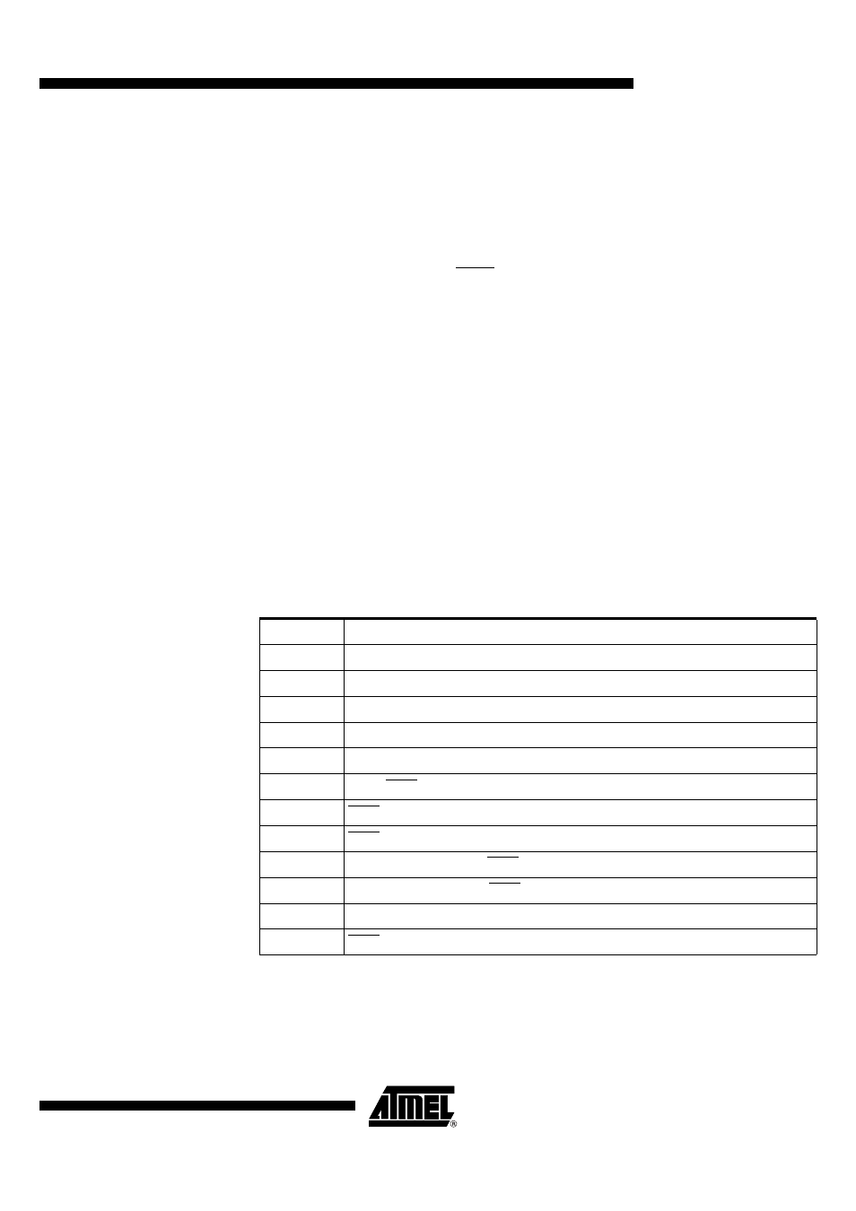
External Program Memory
Characteristics
Table 114. Symbol Description
Symbol
Parameter
T
CPU clock period (F
CK_CPU
)
T
LHLL
ALE pulse width
T
AVLL
Address Valid to ALE
T
LLAX
Address Hold After ALE
T
LLIV
ALE to Valid Instruction In
T
LLPL
ALE to PSEN
T
PLPH
PSEN Pulse Width
T
PLIV
PSEN to Valid Instruction In
T
PXIX
Input Instruction Hold After PSEN
T
PXIZ
Input Instruction Float After PSEN
T
AVIV
Address to Valid Instruction In
T
PLAZ
PSEN Low to Address Float