Typical applications, Recommended external components – Rainbow Electronics AT89C5122 User Manual
Page 17
17
AT8xC5122/23
4202E–SCR–06/06
Typical Applications
Recommended External components
All the external components described in the figure and table below must be imple-
mented as close as possible from the microcontroller package.
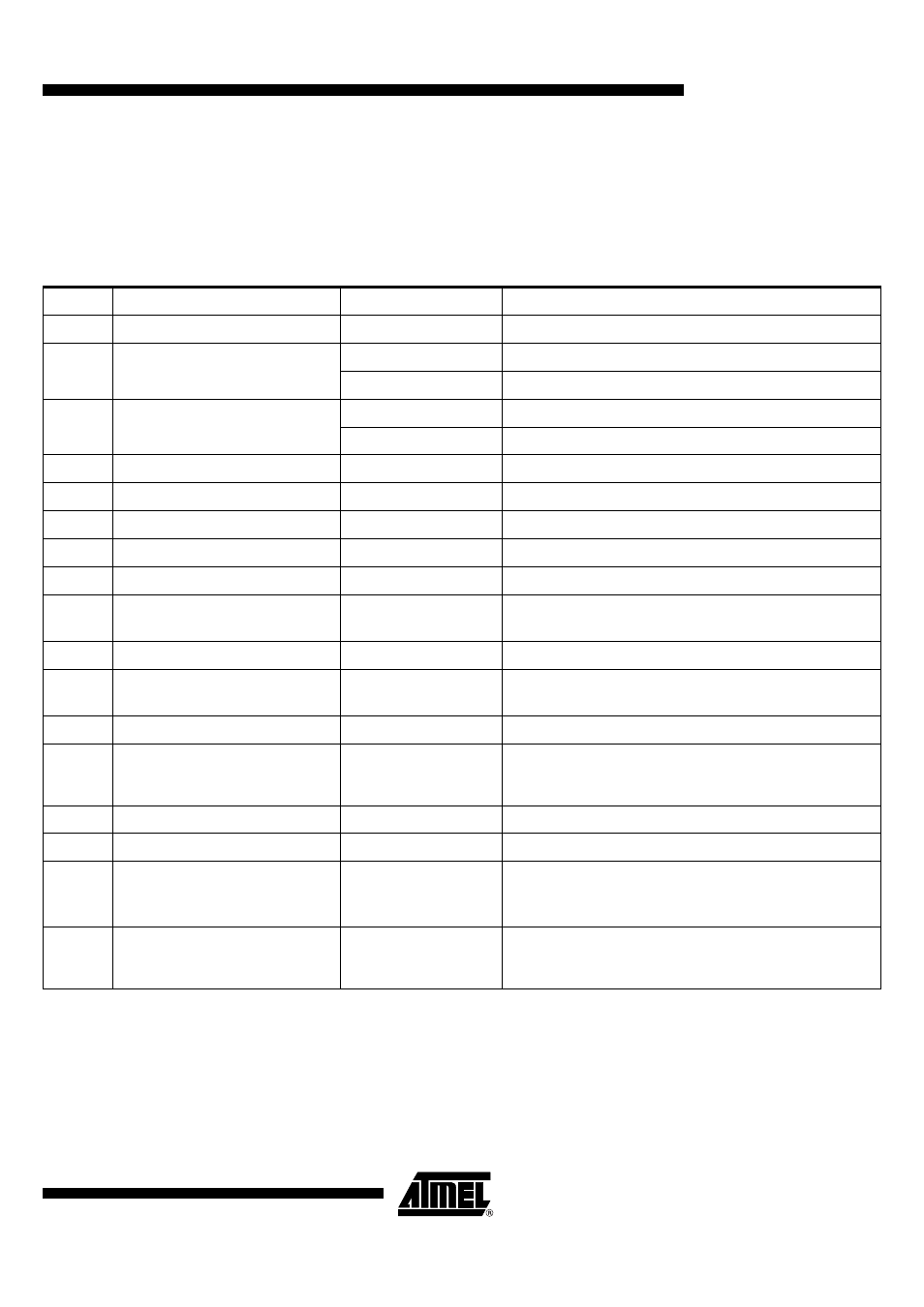
Table 3. External Components Bill Of Materials
Reference Description
Value
Comments
R1
USB Full Speed Pull-up
1.5 K
Ω
+/-10%
All product versions
R2
USB pad serial resistor
27
Ω
+/-10%
For AT8xC5122 versions
33
Ω
+/-10%
For AT83C5123 versions
R3
USB pad serial resistor
27
Ω
+/-10%
For AT8xC5122 versions
33
Ω
+/-10%
For AT83C5123 versions
R4
PLL filter resistor
1.8 K
Ω
+/-10%
All product versions
R5
CIO Pull-up resistor
10 K
Ω
+/10%
All product versions
C1
Power Supply filter capacitor
100 nF +80/-20%
All product versions
C2
PLL filter capacitor
33 pF +/-10%
All product versions
C3
PLL filter capacitor
150 pF +/-10%
All product versions
C4
USB pad decoupling capacitor
680 nF +/-30%
All product versions.
If USB interface is not used, this capacitor is optional
C5
Smart Card clock filter capacitor
27 pF +/-10%
All product versions.
C6
DC/DC Converter decoupling capacitor
10 µF +/-10%
Low ESR
All product versions.
This capacitor does not impact the USB Inrush Current
C7
DC/DC Converter filter capacitor
100 nF +80/-20%
All product versions
C8
Power Supply decoupling capacitor
4.7 µF +/-10%
All products versions
This capacitor impacts the USB Inrush Current. Maximum
application capacitance allowed by the USB standard is 10 µF.
C9
Power Supply filter capacitor
100 nF +80/-20C
All product versions
C10
Reset capacitor
10 µF +/-10%
Optional capacitor for all product versions
L1
DC/DC converter input inductance
10 µH +/- 10%
Min rated current : 200 mA
Min rated freq. : 4 MHz
All product versions.
Qualified component : Murata LQH32CN100K21L
If DC/DC converter is not used at 5V, this inductance is optional.
Q1
Crystal
8.0000 Mhz +/- 2500 ppm
max
ESR max : 100
Ω
All product versions