Rainbow Electronics 71M6542G User Manual
Data sheet, General description, Features
71M6541D/71M6541F/71M6542F
Energy Meter ICs
DATA SHEET
April 2011
v1.1
© 2008–2011 Teridian Semiconductor Corporation
1
A Maxim Integrated Products Brand
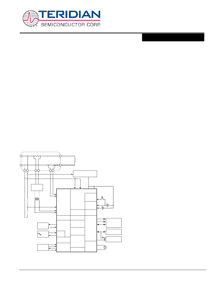
GENERAL DESCRIPTION
The 71M6541D/71M6541F/71M6542F are Teridian’s 4th-generation
single-phase metering SoCs with a 5MHz 8051-compatible MPU core,
low-power RTC with digital temperature compensation, flash memory,
and LCD driver. Our Single Converter Technology® with a 22-bit delta-
sigma ADC, three or four analog inputs, digital temperature com-
pensation, precision voltage reference, and a 32-bit computation
engine (CE) supports a wide range of metering applications with
very few external components.
The 71M6541D/71M6541F/71M6542F support optional interfaces to
the Teridian 71M6x01 series of isolated sensors, which offer BOM
cost reduction, immunity to magnetic tamper, and enhanced
reliability. Other features include an SPI™ interface, advanced
power management, ultra-low-power operation in active and battery
modes, 3/5KB shared RAM and 32/64KB of flash memory that can be
programmed in the field with code and/or data during meter
operation and the ability to drive up to six LCD segments per SEG
driver pin. High processing and sampling rates combined with
differential inputs offer a powerful metering platform for residential
meters.
A complete array of code development tools, demonstration code,
and reference designs enable rapid development and certification of
meters that meet all ANSI and IEC electricity metering standards
worldwide.
MPU
RTC
TIMERS
IAP
VA
IBP
XIN
XOUT
RX
TX
TX
RX
COM0...5
V3P3A V3P3SYS
VBAT
VBAT_RTC
SEG
GNDA GNDD
SEG/DIO
DIO
ICE
LINE
NEUTRAL
LOAD
8888.8888
PULSES,
DIO
IR
AMR
POWER FAULT
COMPARATOR
MODUL-
ATOR
SERIAL PORTS
OSCILLATOR/
PLL
MUX and ADC
LCD DRIVER
DIO, PULSES
COMPUTE
ENGINE
FLASH
MEMORY
RAM
32 kHz
REGULATOR
Shunt
POWER SUPPLY
TERIDIAN
71M6541D/F
TEMPERATURE
SENSOR
VREF
BATTERY
PWR MODE
CONTROL
WAKE-UP
NEUTRAL
I
2
C or µWire
EEPROM
IAN
IBN
RTC
BATTERY
V3P3D
BATTERY
MONITOR
SPI INTERFACE
HOST
LCD DISPLAY
Resistor Divider
Pulse
Trans-
former
TERIDIAN
71M6xx1
Shunt
LINE
LINE
Note:
This system is referenced to LINE
11/5/2010
FEATURES
• 0.1% Accuracy Over 2000:1 Current Range
• Exceeds IEC 62053/ANSI C12.20 Standards
• Two Current Sensor Inputs with Selectable
Differential Mode
• Selectable Gain of 1 or 8 for One Current Input
to Support Shunts
• High-Speed Wh/VARh Pulse Outputs with
Programmable Width
• 32KB Flash, 3KB RAM (71M6541D)
• 64KB Flash, 5KB RAM (71M6541F/42F)
• Up to Four Pulse Outputs with Pulse Count
• Four-Quadrant Metering
• Digital Temperature Compensation:
-
Metrology Compensation
-
Accurate RTC for TOU Functions with
Automatic Temperature Compensation
for Crystal in All Power Modes
• Independent 32-Bit Compute Engine
• 46-64Hz Line Frequency Range with the Same
Calibration
• Phase Compensation (±10°)
• Three Battery-Backup Modes:
-
Brownout Mode (BRN)
-
LCD Mode (LCD)
-
Sleep Mode (SLP)
• Wake-Up on Pin Events and Wake-On Timer
• 1µA in Sleep Mode
• Flash Security
• In-System Program Update
• 8-Bit MPU (80515), Up to 5 MIPS
• Full-Speed MPU Clock in Brownout Mode
• LCD Driver:
- Up to 6 Commons/Up to 56 Pins
• 5V LCD Driver with DAC
• Up to 51 Multifunction DIO Pins
• Hardware Watchdog Timer (WDT)
• I
2
C/MICROWIRE™ EEPROM Interface
• SPI Interface with Flash Program Capability
• Two UARTs for IR and AMR
• IR LED Driver with Modulation
• Industrial Temperature Range
•
64-Pin (71M6541D/71M6541F) and 100-pin
(71M6542F) Lead(Pb)-Free LQFP Package
19-5376; Rev 1.1; 4/11
Single Converter Technology is a registered trademark of Maxim Integrated
Products, Inc.
SPI is a trademark of Motorola, Inc.
MICROWIRE is a trademark of National Semiconductor Corp.
Document Outline
- 1 Introduction
- 2 Hardware Description
- 2.1 Hardware Overview
- 2.2 Analog Front End (AFE)
- 2.3 Digital Computation Engine (CE)
- 2.4 80515 MPU Core
- 2.5 On-Chip Resources
- 2.5.1 Physical Memory
- 2.5.2 Oscillator
- 2.5.3 PLL and Internal Clocks
- 2.5.4 Real-Time Clock (RTC)
- 2.5.5 71M654x Temperature Sensor
- 2.5.6 71M654x Battery Monitor
- 2.5.7 UART and Optical Interface
- 2.5.8 Digital I/O and LCD Segment Drivers
- 2.5.9 EEPROM Interface
- 2.5.10 SPI Slave Port
- 2.5.11 Hardware Watchdog Timer
- 2.5.12 Test Ports (TMUXOUT and TMUX2OUT Pins)
- 3 Functional Description
- 4 Application Information
- 4.1 Connecting 5 V Devices
- 4.2 Direct Connection of Sensors
- 4.3 71M6541D/F Using Local Sensors
- 4.4 71M6541D/F Using 71M6x01and Current Shunts
- 4.5 71M6542F Using Local Sensors
- 4.6 71M6542F Using 71M6x01 and Current Shunts
- 4.7 Metrology Temperature Compensation
- 4.8 Connecting I2C EEPROMs
- 4.9 Connecting Three-Wire EEPROMs
- 4.10 UART0 (TX/RX)
- 4.11 Optical Interface (UART1)
- 4.12 Connecting the Reset Pin
- 4.13 Connecting the Emulator Port Pins
- 4.14 Flash Programming
- 4.15 MPU Firmware Library
- 4.16 Crystal Oscillator
- 4.17 Meter Calibration
- 5 Firmware Interface
- 5.1 I/O RAM Map –Functional Order
- 5.2 I/O RAM Map – Alphabetical Order
- 5.3 CE Interface Description
- 6 Electrical Specifications
- 6.1 Absolute Maximum Ratings
- 6.2 Recommended External Components
- 6.3 Recommended Operating Conditions
- 6.4 Performance Specifications
- 6.4.1 Input Logic Levels
- 6.4.2 Output Logic Levels
- 6.4.3 Battery Monitor
- 6.4.4 Temperature Monitor
- 6.4.5 Supply Current
- 6.4.6 V3P3D Switch
- 6.4.7 Internal Power Fault Comparators
- 6.4.8 2.5 V Voltage Regulator – System Power
- 6.4.9 2.5 V Voltage Regulator – Battery Power
- 6.4.10 Crystal Oscillator
- 6.4.11 Phase-Locked Loop (PLL)
- 6.4.12 LCD Drivers
- 6.4.13 VLCD Generator
- 6.4.14 VREF
- 6.4.15 ADC Converter
- 6.4.16 Pre-Amplifier for IAP-IAN
- 6.5 Timing Specifications
- 6.6 Package Outline Drawings
- 6.7 Pinout Diagrams
- 6.8 Pin Descriptions
- 7 Ordering Information
- 8 Related Information
- 9 Contact Information
- Appendix A: Acronyms
- Appendix B: Revision History