Rainbow Electronics AT89C5122 User Manual
Page 25
25
AT8xC5122/23
4202E–SCR–06/06
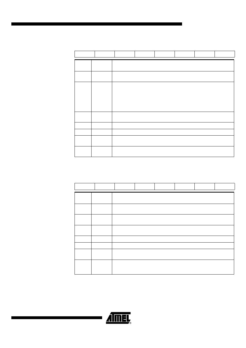
Table 6. Auxiliary Register 1 AUXR1- (0A2h) for AT8xC5122
Reset Value = XX1X XX0X0b (Not bit addressable)
Table 7. Auxiliary Register 1 AUXR1- (0A2h) for AT83C5123
Reset Value = XXXX XX0X0b (Not bit addressable)
7
6
5
4
3
2
1
0
-
-
ENBOOT
-
GF3
0
-
DPS
Bit
Number
Bit
Mnemonic
Description
7 - 6
-
Reserved
The value read from this bit is indeterminate. Do not change these bits.
5
ENBOOT
Enable Boot ROM (CRAM / E2PROM version only)
Set this bit to map the Boot ROM from 8000h to FFFFh. If the PC increments
beyond 7FFFh address, the code is fetch from internal ROM
Clear this bit to disable Boot ROM. If the PC increments beyond 7FFFh address,
the code is fetch from external code memory (C51 standard roll over function)
This bit is forced to 1 at reset
4
-
Reserved
The value read from this bit is indeterminate. Do not change this bit.
3
GF3
This bit is a general-purpose user flag.
2
0
Always cleared.
1
-
Reserved
The value read from this bit is indeterminate. Do not change this bit.
0
DPS
Data Pointer Selection
Cleared to select DPTR0. Set to select DPTR1.
7
6
5
4
3
2
1
0
-
-
-
-
GF3
0
-
DPS
Bit
Number
Bit
Mnemonic
Description
7 - 6
-
Reserved
The value read from this bit is indeterminate. Do not change these bits.
5
Reserved
The value read from this bit is indeterminate. Do not change these bits.
4
-
Reserved
The value read from this bit is indeterminate. Do not change this bit.
3
GF3
This bit is a general-purpose user flag.
2
0
Always cleared.
1
-
Reserved
The value read from this bit is indeterminate. Do not change this bit.
0
DPS
Data Pointer Selection
Cleared to select DPTR0.
Set to select DPTR1.