Rainbow Electronics MAX13256 User Manual
General description, Benefits and features, Applications
MAX13256
36V H-Bridge Transformer
Driver for Isolated Supplies
����������������������������������������������������������������� Maxim Integrated Products 1
General Description
The MAX13256 H-bridge transformer driver provides a
simple solution for making isolated power supplies up to
10W. The device drives a transformer’s primary coil with
up to 300mA of current from a wide 8V to 36V DC sup-
ply. The transformer’s secondary-to-primary winding ratio
defines the output voltage, allowing selection of virtually
any isolated output voltage.
The device features adjustable current limiting, allowing
indirect limiting of secondary-side load currents. The cur-
rent limit of the MAX13256 is set by an external resistor. A
FAULT output asserts when the device detects an overtem-
perature or overcurrent condition. In addition, the device
features a low-power mode to reduce the overall supply
current to 0.65mA (typ) when the driver is not in use.
The device can be operated using the internal oscillator
or driven by an external clock to synchronize multiple
MAX13256 devices and precisely set the switching fre-
quency. Internal circuitry guarantees a fixed 50% duty
cycle to prevent DC current flow through the transformer,
regardless of which clock source is used.
The device is available in a small 10-pin (3mm x 3mm)
TDFN package and is specified over the -40NC to +125NC
automotive temperature range.
Benefits and Features
S
Simple, Flexible Design
8V to 36V Supply Range
Up to 90% Efficiency
Provides Up to 10W to the Transformer
Undervoltage Lockout
2.5V to 5V Compatible Logic Interface
Internal or External Clock Source
Adjustable Overcurrent Threshold
S
Integrated System Protection
Fault Detection and Indication
Overcurrent Limiting
Overtemperature Protection
S
Saves Space on Board
Small 10-Pin TDFN Package (3mm x 3mm)
Applications
Power Meters
Isolated Fieldbus Interfaces
24V PLC Supply Isolation
Medical Equipment
Motor Controls
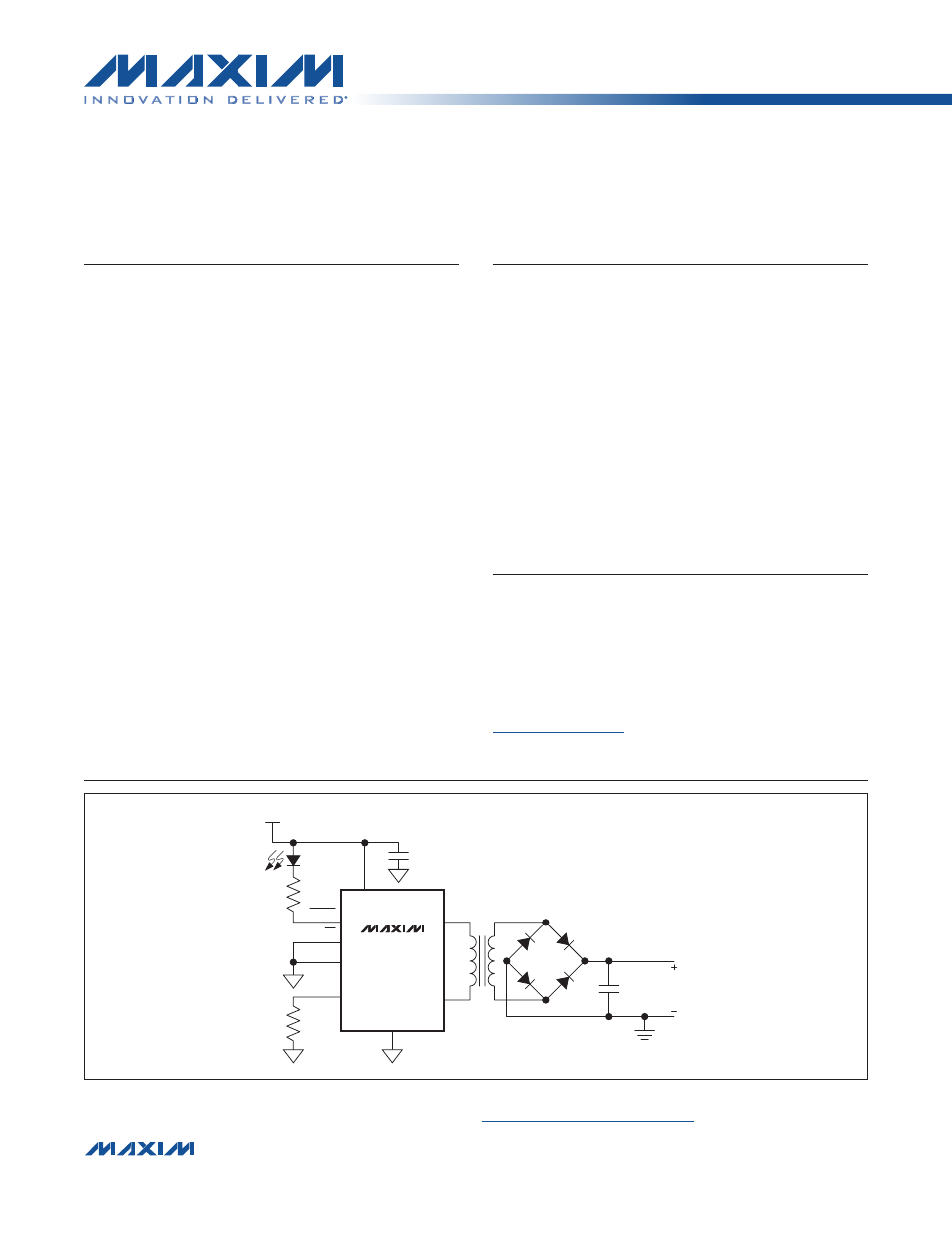
Typical Operating Circuit
19-5847; Rev 1; 8/11
appears at end of data sheet.
For related parts and recommended products to use with this part, refer to:
www.maxim-ic.com/MAX13256.related
E V A L U A T I O N K I T A V A I L A B L E
FAULT
1µF
0.1µF
+24V
4.6kI
R
LIM
V
DD
EN
CLK
ST2
GND
ST1
ITH
ISOLATED
V
OUT
MAX13256
For pricing, delivery, and ordering information, please contact Maxim Direct at 1-888-629-4642,
or visit Maxim’s website at www.maxim-ic.com.
Document Outline
- General Description
- Benefits and Features
- Applications
- Typical Operating Circuit
- Absolute Maximum Ratings
- Package Thermal Characteristics
- Electrical Characteristics
- Test Circuits/Timing Diagrams
- Typical Operating Characteristics
- Pin Configuration
- Pin Description
- Functional Diagram
- Detailed Description
- Applications Information
- Component Selection
- Ordering Information
- Chip Information
- Package Information
- Revision History
- LIST OF FIGURES
- Figure 1. Test Circuits (A and B) and Timing Diagram (C) for Rise, Fall, and Dead Times
- Figure 2. Timing Diagram for Current Limiting
- Figure 3. Output Snubber
- Figure 4. Secondary-Side Rectification Topologies
- Figure 5. Output Ripple Filtering
- Figure 6. +24V to Isolated Regulated +5V
- Figure 7. +24V to Isolated Regulated +3.3V
- Figure 8. +24V to Isolated Regulated +12V
- Figure 9. +24V to Isolated Regulated ±15V
- Figure 10. Isolated Power Supply for Industrial Control Applications
- LIST OF TABLES