Clock controller, On-chip oscillator, Quartz specification – Rainbow Electronics AT89C5122 User Manual
Page 41
41
AT8xC5122/23
4202E–SCR–06/06
Clock Controller
The clock controller is based on an on-chip oscillator feeding an on-chip Phase Lock
Loop (PLL). All the internal clocks to the CPU core and peripherals are generated by this
controller.
On-Chip Oscillator
The on-chip oscillator is composed of a single-stage inverter and a parallel feedback
resistor. The XTAL1 and XTAL2 pins are respectively the input and the output of the
inverter, which can be configured with off-chip components as a Pierce oscillator (see
Figure 16).
The on-chip oscillator has been designed and optimized to work with an external 8 MHz
crystal and very few load capacitance. Then external load capacitors are not needed
given that :
–
the internal capacitance of the microcontroller and the stray capacitance of
circuit board are enough to ensure a stable oscillation
–
a very high accuracy on the oscillation frequency is not needed
The circuit works on its fundamental frequency at 8 MHz.
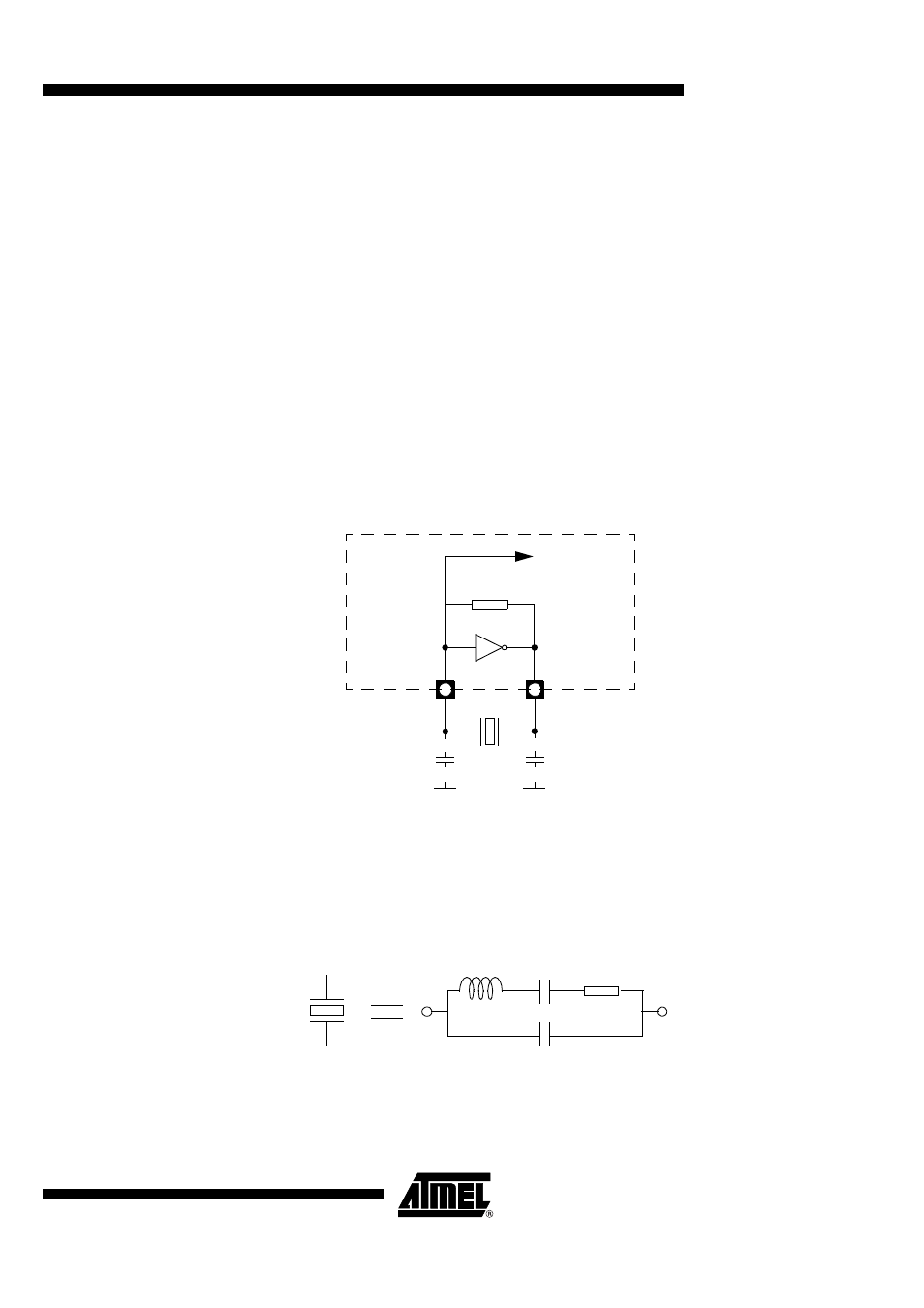
Figure 16. Oscillator Schematic
C1 and C2 represents the internal capacitance of the microcontroller and the stray
capacitance of the circuit board. It is recommended to implement the crystal as close as
possible from the microcontroller package.
Quartz Specification
The equivalent circuit of a crystal is represented on the figure below :
The Equivalent Serial Resistance R1 must be lower than 100 Ohm.
Feedback
Resistor
XTAL1
XTAL2
8 MHz
GND
GND
Microcontroller
C1
C2
To internal
clock circuitry
L1
C1
R1
C0