Rainbow Electronics AT89C5122 User Manual
Page 144
144
AT8xC5122/23
4202E–SCR–06/06
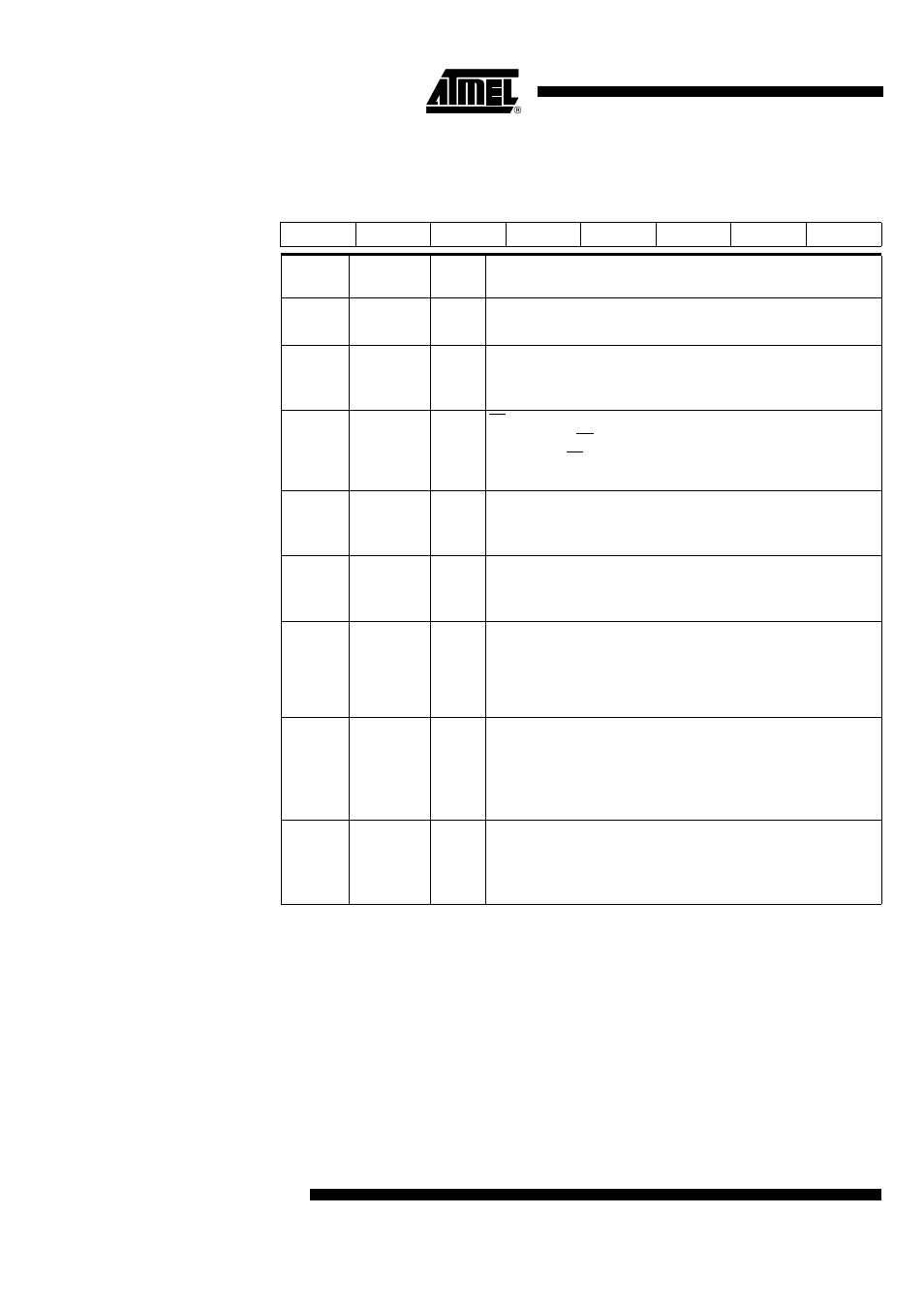
Reset Value = 00010100b
Table 85. Serial Peripheral Control Register - SPCON (C3h)
7
6
5
4
3
2
1
0
SPR2
SPEN
SSDIS
MSTR
CPOL
CPHA
SPR1
SPR0
Bit
Number
Bit
Mnemonic
R/W
Mode
Description
7
SPR2
RW
Serial Peripheral Rate 2
Bit with SPR1 and SPR0 define the clock rate
6
SPEN
RW
Serial Peripheral Enable
Clear to disable the SPI interface (internal reset of the SPI)
Set to enable the SPI interface
5
SSDIS
RW
SS Disable
Clear to enable SS in both Master and Slave modes
Set to disable SS in both Master and Slave modes. In Slave mode, this
bit has no effect if CPHA = ’0’
4
MSTR
RW
Serial Peripheral Master
Clear to configure the SPI as a Slave
Set to configure the SPI as a Master
3
CPOL
RW
Clock Polarity
Clear to have the SCK set to ’0’ in idle state
Set to have the SCK set to ’1’ in idle low
2
CPHA
RW
Clock Phase
Clear to have the data sampled when the SPSCK leaves the idle state
(see CPOL)
Set to have the data sampled when the SPSCK returns to idle state
(see CPOL)
1
SPR1
RW
Serial Peripheral Rate (SPR2:SPR1:SPR0)
000: Reserved
001: F
CK_SPI
/4
010: F
CK_SPI
/8
011: F
CK_SPI
/16
0
SPR0
RW
100: F
CK_SPI
/32
101: F
CK_SPI
/64
110: F
CK_SPI
/128
111: Reserved