Mode 0 (13-bit timer), Mode 1 (16-bit timer), Figure 90 t – Rainbow Electronics AT89C5122 User Manual
Page 148
148
AT8xC5122/23
4202E–SCR–06/06
For normal Timer operation (GATE0= 0), setting TR0 allows TL0 to be incremented by
the selected input. Setting GATE0 and TR0 allows external pin INT0# to control Timer
operation.
Timer 0 overflow (count rolls over from all 1s to all 0s) sets the TF0 flag and generates
an interrupt request.
It is important to stop the Timer/Counter before changing modes.
Mode 0 (13-bit Timer)
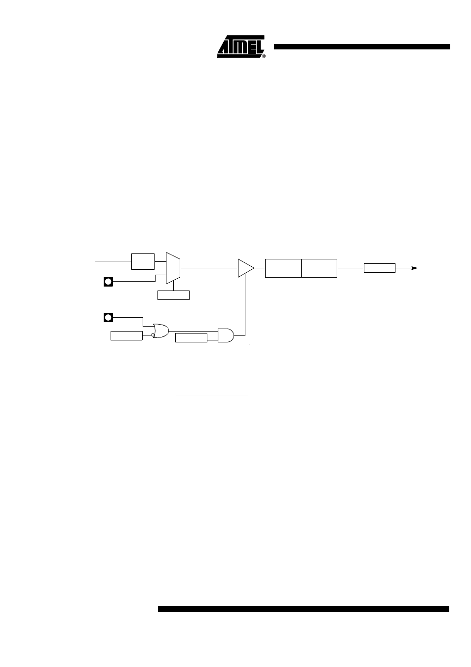
Mode 0 configures Timer 0 as a 13-bit Timer which is set up as an 8-bit Timer (TH0 reg-
ister) with a modulo-32 prescaler implemented with the lower five bits of the TL0 register
(see Figure 90). The upper three bits of the TL0 register are indeterminate and should
be ignored. Prescaler overflow increments the TH0 register.
Figure 91 gives the overflow period calculation formula.
Figure 90. Timer/Counter x (x= 0 or 1) in Mode 0
Figure 91. Mode 0 Overflow Period Formula
Mode 1 (16-bit Timer)
Mode 1 configures Timer 0 as a 16-bit Timer with the TH0 and TL0 registers connected
in a cascade (see Figure 92). The selected input increments the TL0 register.
Figure 93 gives the overflow period calculation formula when in timer mode.
TRx
TCON reg
TFx
TCON reg
0
1
GATEx
TMOD reg
Overflow
Timer x
Interrupt
Request
C/Tx#
TMOD reg
TLx
(5 bits)
THx
(8 bits)
INTx#
Tx
FCK_Tx
/6
6
⋅
(16384 – (THx, TLx))
TFx
PER
=
F
CK_Tx