Smart card interface, Entering in power-down mode, Exiting from power-down mode – Rainbow Electronics AT89C5122 User Manual
Page 183
183
AT8xC5122/23
4202E–SCR–06/06
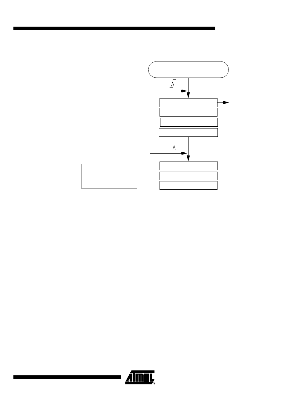
Figure 110. Example of a Suspend/Resume Management
Smart Card Interface
Entering in Power-down Mode
In order to reduce the power consumption, a power-down or idle mode can be invoked
by software (see Table 13, PCON register). Before activating these modes the applica-
tion will need to:
Power-off the Smart Card Interface by applying the following sequence:
•
Set CRST pin at low level by clearing the bit CARDRST in SCCON register.
•
Set CCLK pin at low level by clearing the bit CLK then the CARDCLK in SCCON
register.
•
Set CIO pin at low level by clearing the bit UART in SCICR register then the bit
CARDIO in SCCON register.
•
Power the Smart Interface off by clearing the CARDVCC bit in SCCON register. This
instruction enables to switch DC/DC converter off.
CPRES input:
•
Set the bit PRSEN in ISEL register
•
Set the bit EX1 in IE0 register
•
Set the bit EA in the IE0 register
•
Invert the bit CPLEV in ISEL register (INT1 interrupt vector)
•
Clear the bit PRESIT in the ISEL register
Exiting from Power-down
Mode
The microcontroller will exit from Power-down or Idle modes upon a reset or INT1 inter-
rupt which is a multiplexing of the interruptions generated by the CPRES pin (Card
detection), RxD flag (UART reception) and INT1 pin.
USB Controller Init
Detection of a SUSPEND State
SPINT
Set SUSPCLK
Disable PLL
microcontroller in power-down
Detection of a RESUME State
WUPCPU
Enable PLL
Clear SUSPCLK
Clear WUPCPU bit
Clear SPINT
Note :
WUPCPU bit must be
Cleared before enabling
the PLL
Put the USB pads
in power down mode