Waiting time (wt) counter – Rainbow Electronics AT89C5122 User Manual
Page 69
69
AT8xC5122/23
4202E–SCR–06/06
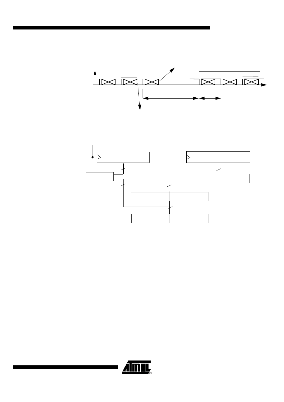
Figure 32. Block Guard Time.
Figure 33. Guard Time and Block Guard Time counters
To illustrate the use of Guard Time and Block Guard Time, let us consider the
ISO/IEC7816-3 recommendation : Guard Time = 2 (minimum delay between 2 consecu-
tive characters sent by the Terminal = 12 ETUs), and Block Guard Time = 22 ETUs.
After A smart Card Reset
–
Write 00decimal in SCGT1, Write 21decimal in SCGT0
–
Set BGTEN in SCSR (BGTEN was 0 before as a result of the smart card
reset)
–
Write 12decimal in SCGT0
Now the Guard Time and Block Guard Time are properly initialized. The TERMINAL will
insure a minimun 12 ETUs between 2 leading edges of 2 consecutive characters trans-
mitted. The TERMINAL will also insure a minimum of 22 ETUs between the leading
edge of a character sent by the ICC, and the leading edge of a character sent by the
TERMINAL. There is no need to write SCGT1,0 again and again.
Waiting Time (WT) Counter
The WT counter is a 32 bits down counter which can be loaded with the value contained
in the SCWT3, SCWT2, SCWT1, SCWT0 registers. Its main purpose is timeout signal
generation. It is 32 bits wide and is decremented at the ETU rate. see Figure 34.
CHAR 1
CHAR 2
CHAR n
CHAR n+1
CHAR n+2
CHAR n+3
>= Block Guard Time
>= SCGT
RECEPTION from ICC
TRANSMISSION to ICC
Write “Block Guard Time” in SCGT1,0
Write SCGT1,0 with
and set BGTEN to transfer the value to the
shadow SCGT1,0 registers
a value for Guard Time
ETU Counter
Block Guard Time Counter
Enable
SCGT1
SCGT0
9 bits
Guard Time Counter
GT[8:0]
Shadow SCGT1
,Shadow SCGT0
9 bits
Comparator
transmit
Comparator
9 bits
9 bits
Enable
transmit