Pulse width modulator mode – Rainbow Electronics AT89C5131 User Manual
Page 78
78
AT89C5131
4136A–USB–03/03
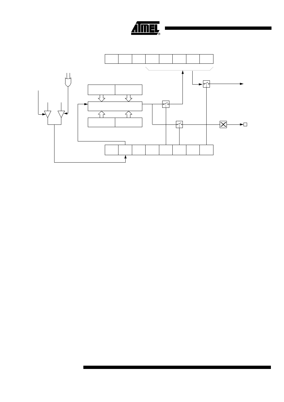
Figure 32. PCA High-speed Output Mode
Before enabling ECOM bit, CCAPnL and CCAPnH should be set with a non zero value,
otherwise an unwanted match could happen.
Once ECOM set, writing CCAPnL will clear ECOM so that an unwanted match doesn’t
occur while modifying the compare value. Writing to CCAPnH will set ECOM. For this
reason, user software should write CCAPnL first, and then CCAPnH. Of course, the
ECOM bit can still be controlled by accessing to CCAPMn register.
Pulse Width Modulator
Mode
All of the PCA modules can be used as PWM outputs. Figure 33 shows the PWM func-
tion. The frequency of the output depends on the source for the PCA timer. All of the
modules will have the same frequency of output because they all share the PCA timer.
The duty cycle of each module is independently variable using the module's capture
register CCAPLn. When the value of the PCA CL SFR is less than the value in the mod-
ule's CCAPLn SFR the output will be low, when it is equal to or greater than the output
will be high. When CL overflows from FF to 00, CCAPLn is reloaded with the value in
CCAPHn. This allows updating the PWM without glitches. The PWM and ECOM bits in
the module's CCAPMn register must be set to enable the PWM mode.
CH
CL
CCAPnH
CCAPnL
ECOMn
CCAPMn, n = 0 to 4
0xDA to 0xDE
CAPNn MATn TOGn PWMn ECCFn
CAPPn
16-bit Comparator
Match
CF
CR
CCON
0xD8
CCF4 CCF3
CCF2
CCF1
CCF0
PCA IT
Enable
CEXn
PCA counter/timer
Write to
CCAPnH
Reset
Write to
CCAPnL
1
0