Configuration – Rainbow Electronics AT89C5131 User Manual
Page 117
117
AT89C5131
4136A–USB–03/03
Configuration
General Configuration
•
USB controller enable
Before any USB transaction, the 48 MHz required by the USB controller must be
correctly generated (See “Clock Controller” on page 19).
The USB controller will be then enabled by setting the EUSB bit in the USBCON
register.
•
Set address
After a Reset or a USB reset, the software has to set the FEN (Function Enable) bit
in the USBADDR register. This action will allow the USB controller to answer to the
requests sent at the address 0.
When a SET_ADDRESS request has been received, the USB controller must only
answer to the address defined by the request. The new address will be stored in the
USBADDR register. The FEN bit and the FADDEN bit in the USBCON register will
be set to allow the USB controller to answer only to requests sent at the new
address.
•
Set configuration
The CONFG bit in the USBCON register will be set after a SET_CONFIGURATION
request with a non-zero value. Otherwise, this bit will be cleared.
Endpoint Configuration
•
Selection of an Endpoint
The endpoint register access is performed using the UEPNUM register. The
registers
–
UEPSTAX
–
UEPCONX
–
UEPDATX
–
UBYCTLX
–
UBYCTHX
These registers correspond to the endpoint whose number is stored in the UEP-
NUM register. To select an Endpoint, the firmware has to write the endpoint number
in the UEPNUM register.
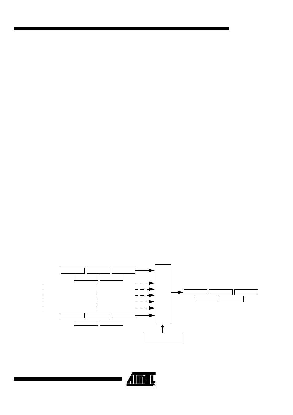
Figure 53. Endpoint Selection
UEPNUM
Endpoint 0
Endpoint 6
UEPSTA0
UEPCON0
UEPDAT0
UEPSTA6
UEPCON6
UEPDAT6
0
1
2
3
4
5
6
SFR registers
UEPSTAX
UEPCONX
UEPDATX
X
UBYCTH0
UBYCTL0
UBYCTH6
UBYCTL6
UBYCTHX
UBYCTLX