Rainbow Electronics AT89C5131 User Manual
Page 70
70
AT89C5131
4136A–USB–03/03
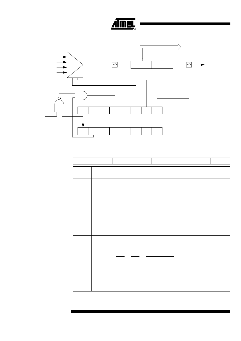
Figure 28. PCA Timer/Counter
Table 52. CMOD Register
CMOD - PCA Counter Mode Register (D9h)
Reset Value = 00XX X000b
Not bit addressable
CIDL
CPS1
CPS0
ECF
It
CH
CL
16 Bit Up/Down Counter
To PCA
modules
F
CLK PERIPH
/6
F
CLK PERIPH
/2
T0 OVF
P1.2
Idle
CMOD
0xD9
WDTE
CF
CR
CCON
0xD8
CCF4 CCF3
CCF2
CCF1
CCF0
overflow
7
6
5
4
3
2
1
0
CIDL
WDTE
-
-
-
CPS1
CPS0
ECF
Bit
Number
Bit
Mnemonic
Description
7
CIDL
Counter Idle Control
Cleared to program the PCA Counter to continue functioning during idle Mode.
Set to program PCA to be gated off during idle.
6
WDTE
Watchdog Timer Enable
Cleared to disable Watchdog Timer function on PCA Module 4.
Set to enable Watchdog Timer function on PCA Module 4.
5
-
Reserved
The value read from this bit is indeterminate. Do not set this bit.
4
-
Reserved
The value read from this bit is indeterminate. Do not set this bit.
3
-
Reserved
The value read from this bit is indeterminate. Do not set this bit.
2
CPS1
PCA Count Pulse Select
CPS1
CPS0
Selected PCA input
0
0
Internal clock f
CLK PERIPH
/6
0
1
Internal clock f
CLK PERIPH
/2
1
0
Timer 0 Overflow
1
1
External clock at ECI/P1.2 pin (max rate = f
CLK PERIPH
/ 4)
1
CPS0
0
ECF
PCA Enable Counter Overflow Interrupt
Cleared to disable CF bit in CCON to inhibit an interrupt.
Set to enable CF bit in CCON to generate an interrupt.