Pca capture mode, Bit software timer/compare mode – Rainbow Electronics AT89C5131 User Manual
Page 76
76
AT89C5131
4136A–USB–03/03
Table 59. CL Register
CL - PCA Counter Register Low (0E9h)
Reset Value = 0000 0000b
Not bit addressable
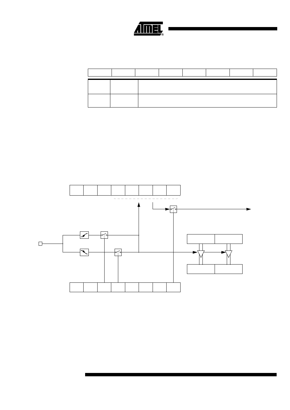
PCA Capture Mode
To use one of the PCA modules in the capture mode either one or both of the CCAPM
bits CAPN and CAPP for that module must be set. The external CEX input for the mod-
ule (on port 1) is sampled for a transition. When a valid transition occurs the PCA
hardware loads the value of the PCA counter registers (CH and CL) into the module’s
capture registers (CCAPnL and CCAPnH). If the CCFn bit for the module in the CCON
SFR and the ECCFn bit in the CCAPMn SFR are set then an interrupt will be generated
(see Figure 30).
Figure 30. PCA Capture Mode
16-bit Software
Timer/Compare Mode
The PCA modules can be used as software timers by setting both the ECOM and MAT
bits in the modules CCAPMn register. The PCA timer will be compared to the module’s
capture registers and when a match occurs an interrupt will occur if the CCFn (CCON
SFR) and the ECCFn (CCAPMn SFR) bits for the module are both set (see Figure 31).
7
6
5
4
3
2
1
0
-
-
-
-
-
-
-
-
Bit
Number
Bit
Mnemonic
Description
7 - 0
-
PCA Counter
CL Value
CF
CR
CCON
0xD8
CH
CL
CCAPnH
CCAPnL
CCF4 CCF3
CCF2
CCF1
CCF0
PCA IT
PCA Counter/Timer
ECOMn
CCAPMn, n = 0 to 4
0xDA to 0xDE
CAPNn MATn TOGn PWMn ECCFn
CAPPn
Cex.n
Capture