Dual data pointer register, Dph(83h) dpl(82h) – Rainbow Electronics AT89C5131 User Manual
Page 24
24
AT89C5131
4136A–USB–03/03
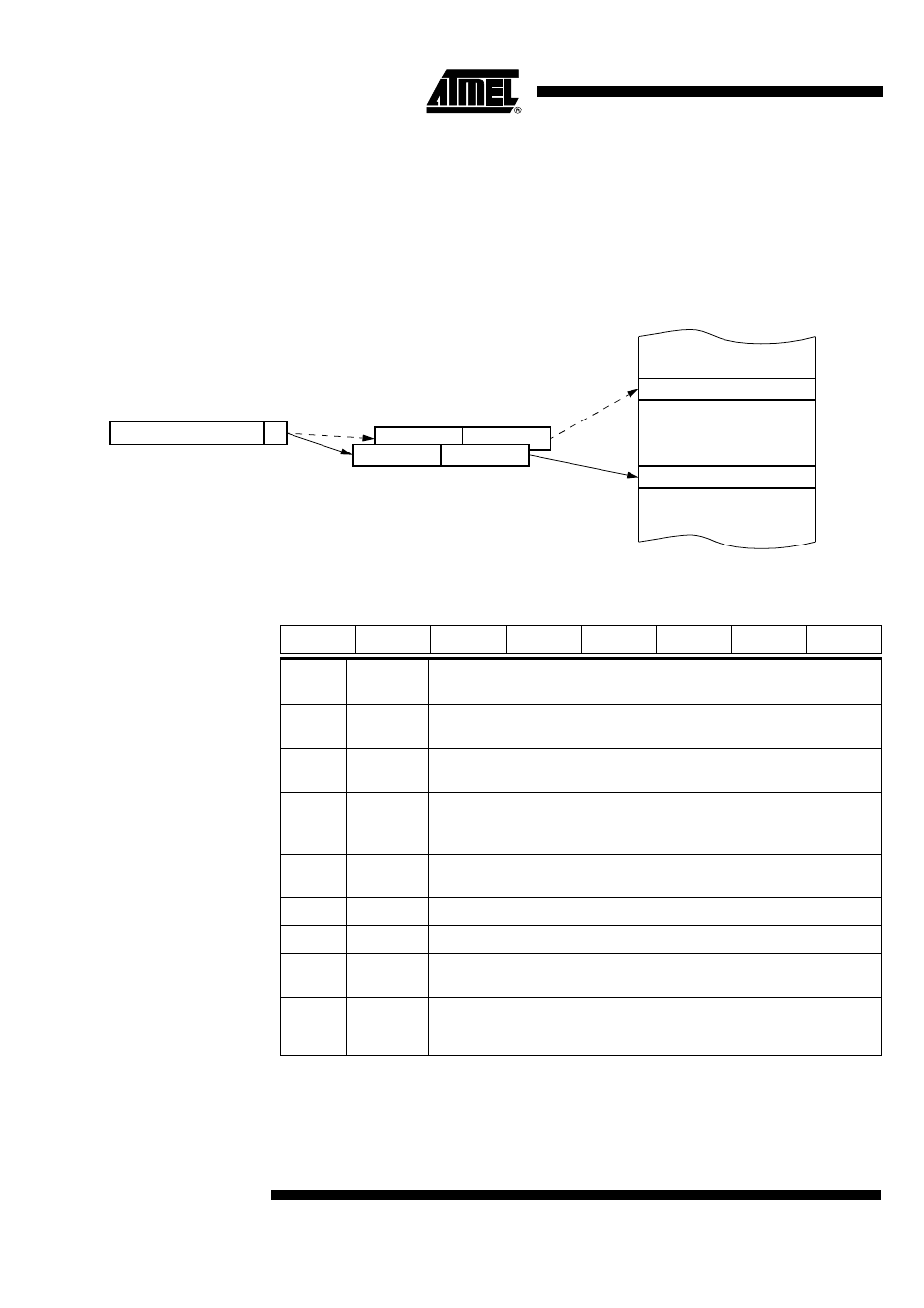
Dual Data Pointer
Register
The additional data pointer can be used to speed up code execution and reduce code
size.
The dual DPTR structure is a way by which the chip will specify the address of an exter-
nal data memory location. There are two 16-bit DPTR registers that address the external
memory, and a single bit called DPS = AUXR1.0 (see Table 30) that allows the program
code to switch between them (see Figure 10).
Figure 10. Use of Dual Pointer
Table 30. AUXR1 Register
AUXR1- Auxiliary Register 1(0A2h)
Reset Value = XXXX XX0X0b
Not bit addressable
a. Bit 2 stuck at 0; this allows to use INC AUXR1 to toggle DPS without changing GF3.
External Data Memory
AUXR1(A2H)
DPS
DPH(83H) DPL(82H)
0
7
DPTR0
DPTR1
7
6
5
4
3
2
1
0
-
-
ENBOOT
-
GF3
0
-
DPS
Bit
Number
Bit
Mnemonic
Description
7
-
Reserved
The value read from this bit is indeterminate. Do not set this bit.
6
-
Reserved
The value read from this bit is indeterminate. Do not set this bit.
5
ENBOOT
Enable Boot Flash
Cleared to disable boot ROM.
Set to map the boot ROM between F800h - 0FFFFh.
4
-
Reserved
The value read from this bit is indeterminate. Do not set this bit.
3
GF3
This bit is a general-purpose user flag.
2
0
Always cleared.
1
-
Reserved
The value read from this bit is indeterminate. Do not set this bit.
0
DPS
Data Pointer Selection
Cleared to select DPTR0.
Set to select DPTR1.