Boot process – Rainbow Electronics AT89C5131 User Manual
Page 40
40
AT89C5131
4136A–USB–03/03
Boot Process
Boot Flash
When the user application programs its own Flash memory, all of the low level details
are handled by a code that is permanently contained in a 3 Kbyte “Boot ROM”. A user
program simply calls the common entry point in the Boot ROM with appropriate parame-
ters to accomplish the desired operation. Boot ROM operations include: erase block,
program byte or page, verify byte or page, program security lock bit, etc. The Boot ROM
is placed in the program memory space at the top of the address space from F800h to
FFFFh (Figure 20).
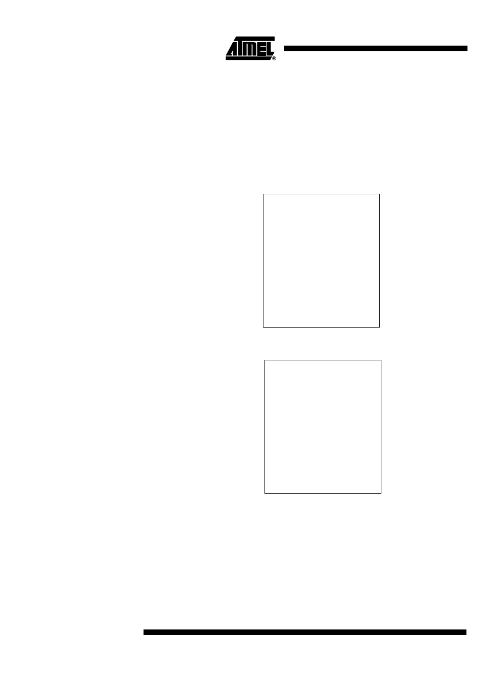
Figure 20. Boot ROM Loader Memory Map
Boot Process Secondary
The boot process is summarized in Figure 21.
FFF0
Entry point for API
ISP start
F400
FFF0
Entry point for API
ISP start
F400
See also other documents in the category Rainbow Electronics Sensors:
- MAX5151 (16 pages)
- MAXQ3108 (64 pages)
- MAX5661 (39 pages)
- MAX6691 (7 pages)
- MAX5362 (12 pages)
- ADC10158 (26 pages)
- MAX8922L (14 pages)
- MAX8596Z (8 pages)
- MAX7491 (18 pages)
- MAX15040 (15 pages)
- MAX5177 (16 pages)
- ADC08138 (22 pages)
- MAX5961 (42 pages)
- T89C51RD2 (86 pages)
- MAX16055 (9 pages)
- MAX6659 (17 pages)
- ADC0820 (20 pages)
- MAX6678 (19 pages)
- MAX8884Z (15 pages)
- MAX16915 (9 pages)
- MAX8620 (18 pages)
- MAX5144 (12 pages)
- MAX6670 (8 pages)
- MAX8760 (39 pages)
- W78C32C (14 pages)
- MX7533 (8 pages)
- MAX8727 (13 pages)
- MAX9053 (15 pages)
- W78C54 (16 pages)
- MAX8614B (15 pages)
- W90N740 (219 pages)
- MAX6626 (13 pages)
- ADC10738 (30 pages)
- MAX17000 (31 pages)
- MAX5051 (21 pages)
- MAXQ1004 (18 pages)
- MAX6871 (51 pages)
- MX7847 (12 pages)
- MAX6608 (6 pages)
- MAX17083 (15 pages)
- MAX6641 (17 pages)
- MAX5251 (16 pages)
- MAX6338 (8 pages)
- MAX6690 (16 pages)
- MAX8668 (18 pages)