Reduced emi mode – Rainbow Electronics AT89C5131 User Manual
Page 151
151
AT89C5131
4136A–USB–03/03
Reduced EMI Mode
The ALE signal is used to demultiplex address and data buses on port 0 when used with
external program or data memory. Nevertheless, during internal code execution, ALE
signal is still generated. In order to reduce EMI, ALE signal can be disabled by setting
AO bit.
The AO bit is located in AUXR register at bit location 0. As soon as AO is set, ALE is no
longer output but remains active during MOVX and MOVC instructions and external
fetches. During ALE disabling, ALE pin is weakly pulled high.
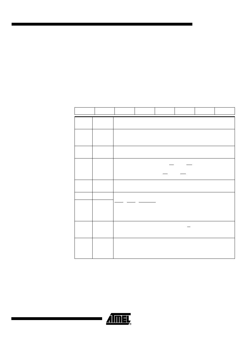
Table 103. AUXR Register
AUXR - Auxiliary Register (8Eh)
Reset Value = 0X0X 1100b
Not bit addressable
7
6
5
4
3
2
1
0
DPU
-
M0
-
XRS1
XRS0
EXTRAM
AO
Bit
Number
Bit
Mnemonic
Description
7
DPU
Disable Weak Pull Up
Cleared to enabled weak pull up on standard Ports
Set to disable weak pull up on standard Ports
6
-
Reserved
The value read from this bit is indeterminate. Do not set this bit.
5
M0
Pulse length
Cleared to stretch MOVX control: the RD and the WR pulse length is 6 clock
periods (default).
Set to stretch MOVX control: the RD and the WR pulse length is 30 clock periods.
4
-
Reserved
The value read from this bit is indeterminate. Do not set this bit.
3
XRS1
XRAM Size
XRS1
XRS0
XRAM size
0
0
256 bytes
0
1
512 bytes
1
0
768 bytes
1
1
1024 bytes (default)
2
XRS0
1
EXTRAM
EXTRAM bit
Cleared to access internal XRAM using MOVX at Ri at DPTR.
Set to access external memory.
0
AO
ALE Output bit
Cleared, ALE is emitted at a constant rate of 1/6 the oscillator frequency (or 1/3 if
X2 mode is used) (default).
Set , ALE is active only during a MOVX or MOVC instruction is used.