Rainbow Electronics AT89C5131 User Manual
Page 72
72
AT89C5131
4136A–USB–03/03
The watchdog timer function is implemented in module 4 (See Figure 31).
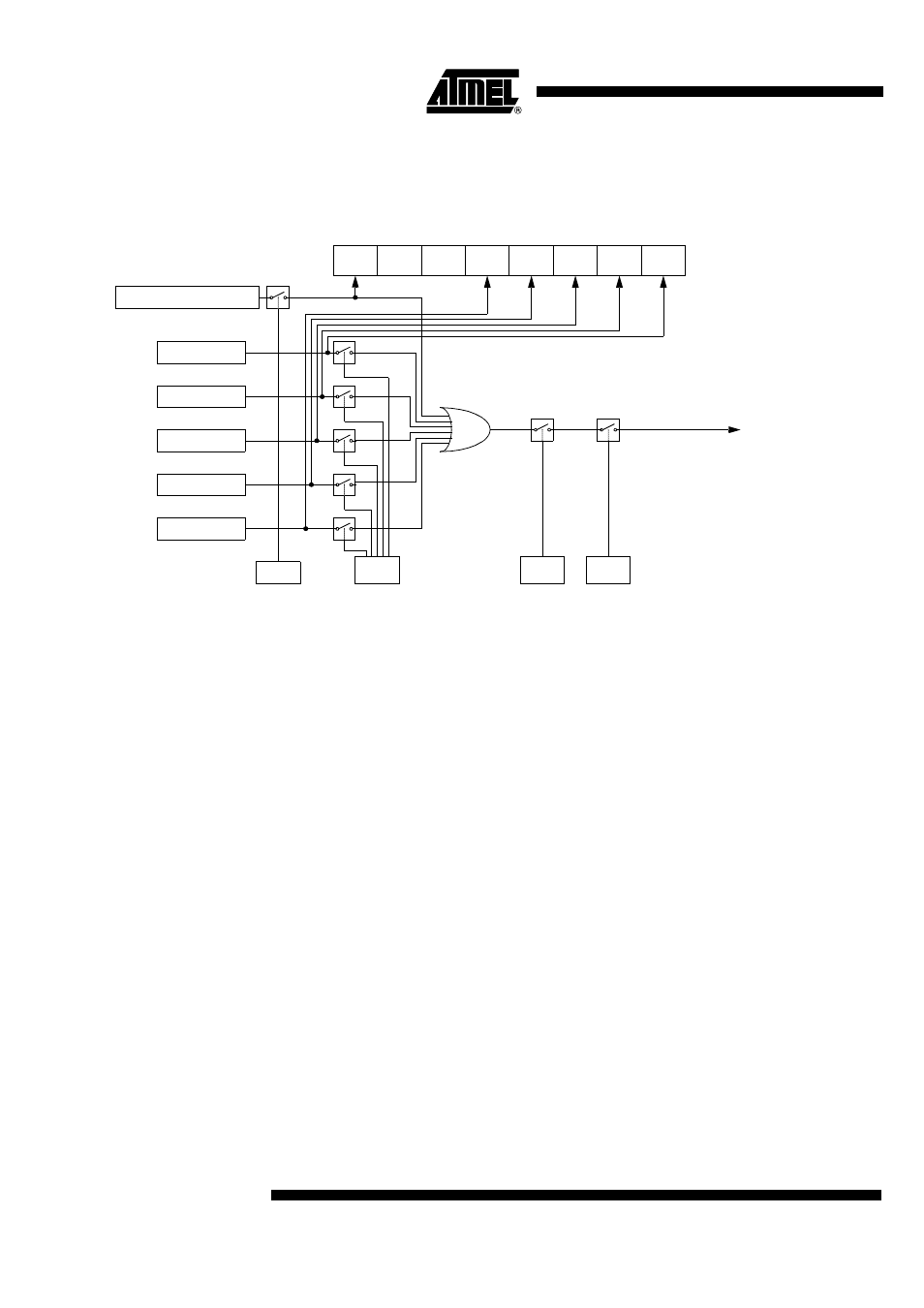
The PCA interrupt system is shown in Figure 29.
Figure 29. PCA Interrupt System
PCA Modules: each one of the five compare/capture modules has six possible func-
tions. It can perform:
•
16-bit capture, positive-edge triggered
•
16-bit capture, negative-edge triggered
•
16-bit capture, both positive and negative-edge triggered
•
16-bit Software Timer
•
16-bit High-speed Output
•
8-bit Pulse Width Modulator
In addition, module 4 can be used as a Watchdog Timer.
Each module in the PCA has a special function register associated with it. These regis-
ters are: CCAPM0 for module 0, CCAPM1 for module 1, etc. (see Table 54). The
registers contain the bits that control the mode that each module will operate in.
•
The ECCF bit (CCAPMn.0 where n = 0, 1, 2, 3, or 4 depending on the module)
enables the CCF flag in the CCON SFR to generate an interrupt when a match or
compare occurs in the associated module.
•
PWM (CCAPMn.1) enables the pulse width modulation mode.
•
The TOG bit (CCAPMn.2) when set causes the CEX output associated with the
module to toggle when there is a match between the PCA counter and the module's
capture/compare register.
•
The match bit MAT (CCAPMn.3) when set will cause the CCFn bit in the CCON
register to be set when there is a match between the PCA counter and the module's
capture/compare register.
•
The next two bits CAPN (CCAPMn.4) and CAPP (CCAPMn.5) determine the edge
that a capture input will be active on. The CAPN bit enables the negative edge, and
CF
CR
CCON
0xD8
CCF4 CCF3
CCF2
CCF1
CCF0
Module 4
Module 3
Module 2
Module 1
Module 0
ECF
PCA Timer/Counter
ECCFn CCAPMn.0
CMOD.0
IE.6
IE.7
To Interrupt
priority decoder
EC
EA