Connection and mounting data, Annex, 18 connection and mounting data – M&C TechGroup SP2000-H320_S2 Operator's manual User Manual
Page 33: 19 annex
33
Gas sampling and gas conditioning technology
2-1.1.4-ME
18
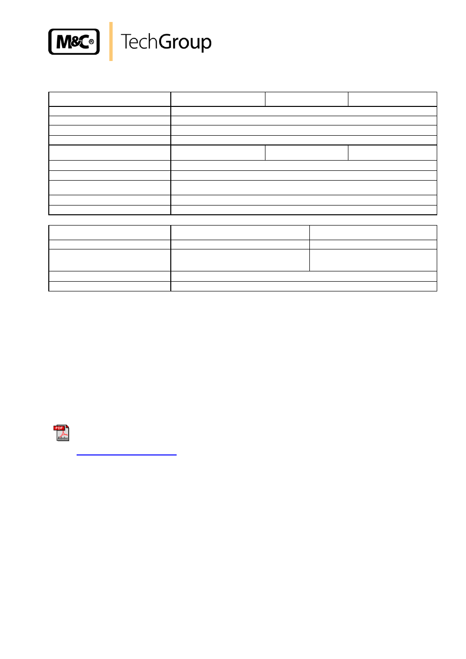
CONNECTION AND MOUNTING DATA
Gas sample probe Type
SP2000-H320/S
SP2000-H320/S1
SP2000-H320/S2
Dimensions B x H x T
340 x 650 x 345
Material filter housing
Stainl. Steel 1.4571*
Sealing material
Graphite
Material probe flange seal
Novapress
Low temperature alarm contact
Capacity: 250V,3A~, 0,25A=,
Switching point:
T 30 °C
See 703
See 703
Connection gas outlet
DN4/6
Connection test gas
Pipe Ø 6 mm
Voltage supply /Capacity /Fuses
230V 50/60Hz, 800W, /115V** = 115V 60Hz, 800W
Fuse 10A
Electrical connection
Terminals max. 4 mm
2
, 2 x M20 x 1,5 cable gland
Mounting flange
DN 65 PN 6, Form B, 1.4571*, > DN or ANSI possible**
Controller Type
703G
703 2-fach
Dimensions B x H x T
150 x 250 x 145
260 x 280 x 140
Status signal output
Low temperature alarm: 1 contact NO, potential
free.
Capacity max. 250V
AC
3A
Low temperature alarm: 2 contacts NO,
potential free.
Capacity max. 250V
AC
3A
Electrical connection
Terminals max. 4 mm
2
, 4 x M20 x 1,5 cable gland
Additional energy
115V 50/60Hz 1725VA, 230V 50/60Hz 3450 VA
* = Standard ** = Option
19
ANNEX
SP2000-H/Filter elements drawing No.: 22551050
High temperature sample tube max. 1800°C drawing No.: 22551040
Electrically heated sample tube SP30-H1.1/-H2 drawing No.: 22091024
SP2000-H320/S, drawing No.: 22551137
SP2000-H320/S1, drawing No.: 225511301
SP2000-H320/S2, drawing No.: 225511303
Further product documentation is available on our internet catalogue: