Figure 15, Figure 16, Positioning of the fixing screws and cable gland – M&C TechGroup SP2000-H320_S2 Operator's manual User Manual
Page 30
30
Gas sampling and gas conditioning technology
2-1.1.4-ME
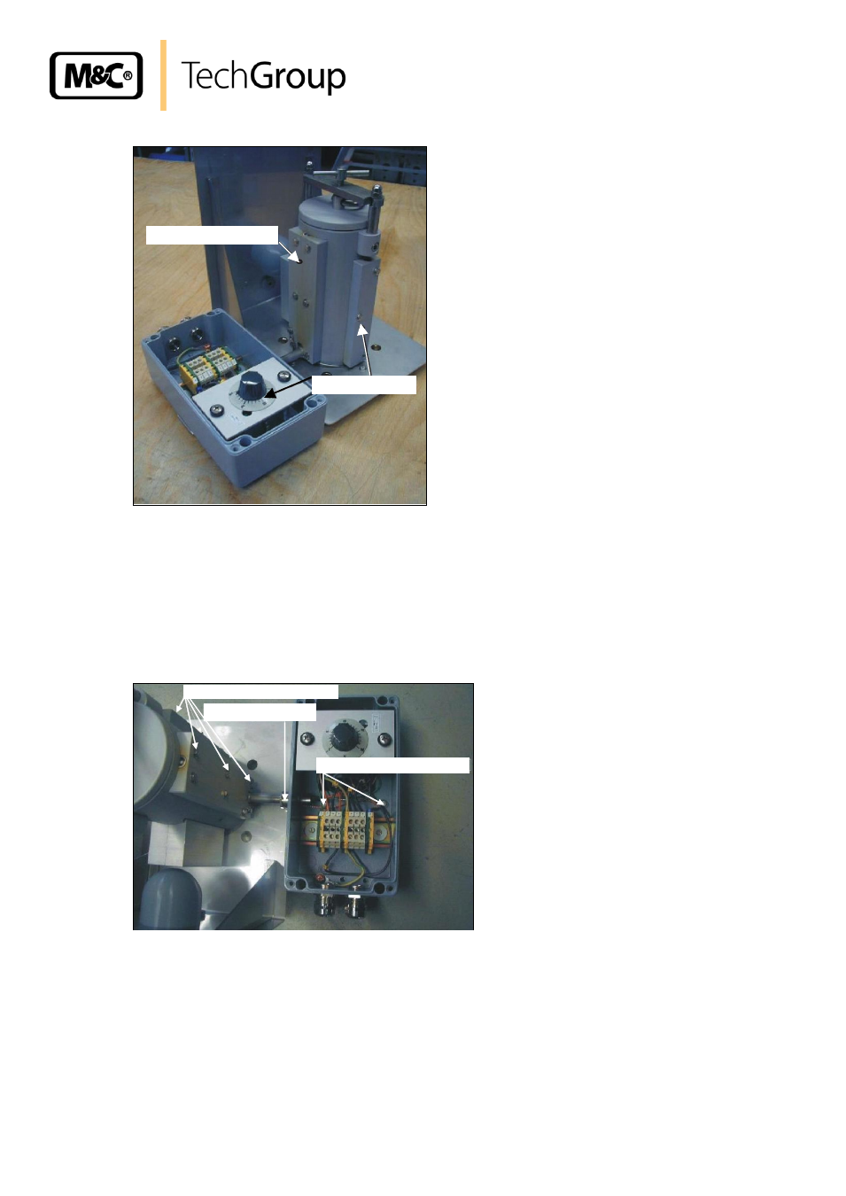
Figure 15 Positioning of the thermostat and heating cartridge
Remove the lid of the electrical connection box after having loosened the 4 screws.
Unscrew both screws “A“ on the bottom of the connection box (figure 16) which are serving to
mount the connection box on to the holding clip.
Unscrew the hexagon head cap screws “B“ (figure 16) which are serving to fix the heating car-
tridge receiving plate and the thermostat sensor receiving plate.
Figure 16 Positioning of the fixing screws and cable gland
Remove the connection box including heating cartridge and thermostat sensor (figure 17)
Loosen the leading-
in cable gland “C“ for the heating cartridge and the capillaries of the ther-
mostat.
Heating cartridge
Thermostat
Hexagon head screws “B“
Cable gland “C“
Hexagon head screws “A“
- SP10 Operator's manual (14 pages)
- N9 KP18 Operator's manual (21 pages)
- SP2000_20SS 150 Data sheet (3 pages)
- SP3100 Data sheet (6 pages)
- PSP4000-H _C _T Data sheet (4 pages)
- SP2200-H_C_I_BB_F Data sheet (2 pages)
- SP35-H... for gas sample probe SP2000-H... Data sheet (2 pages)
- FP-BF Data sheet (2 pages)
- SP3200 Operator's manual (28 pages)
- FPF-0,1 Operator's manual (2 pages)
- PSS-10_1 Operator's manual (23 pages)
- CSS-V2 Data sheet (3 pages)
- PMA 50 EEX Operator's manual (48 pages)
- MP30 Operator's manual (18 pages)
- SP2600-H_C_I_BB_F_0,1GF190 Data sheet (3 pages)
- SR25.1_Ex Operator's manual (22 pages)
- PMA 10S Operator's manual (27 pages)
- CSS-M_W Data sheet (3 pages)
- PAS-500 Operator's manual (20 pages)
- SP2000H320_DIL... Data sheet (3 pages)
- SP3200 Data sheet (6 pages)
- FA-1_2_3,bi Operator's manual (24 pages)
- SR25 Data sheet (2 pages)
- SP3000 Data sheet (4 pages)
- PAS Series Data sheet (2 pages)
- CG Series Data sheet (2 pages)
- ECP 20-2 Data sheet (3 pages)
- MP30-EX Data sheet (2 pages)
- PSP4000-H_C_T Operator's manual (24 pages)
- DIL-U Data sheet (2 pages)
- ADS-So Data sheet (2 pages)
- VC-2-SL Operator's manual (18 pages)
- ECM-ExII Operator's manual (39 pages)
- MP12 Operator's manual (17 pages)
- FPF+ Data sheet (2 pages)
- KS 2.Ex Operator's manual (17 pages)
- PMA 50 EEX Data sheet (3 pages)
- PMA 10S Data sheet (3 pages)
- Gas Sample Probes Series SP Data sheet (2 pages)
- BA-C Operator's manual (16 pages)
- MV3_2-H Series Operator's manual (18 pages)
- VC-2-SL Data sheet (3 pages)
- FM-200K-H_FA Operator's manual (16 pages)
- SP 30-H.._EX2 Operator's manual (16 pages)
- SP2006-H280_DIL Operator's manual (35 pages)