Figure 17, Figure 18, Mechanical stop of the thermostat – M&C TechGroup SP2000-H320_S2 Operator's manual User Manual
Page 31
31
Gas sampling and gas conditioning technology
2-1.1.4-ME
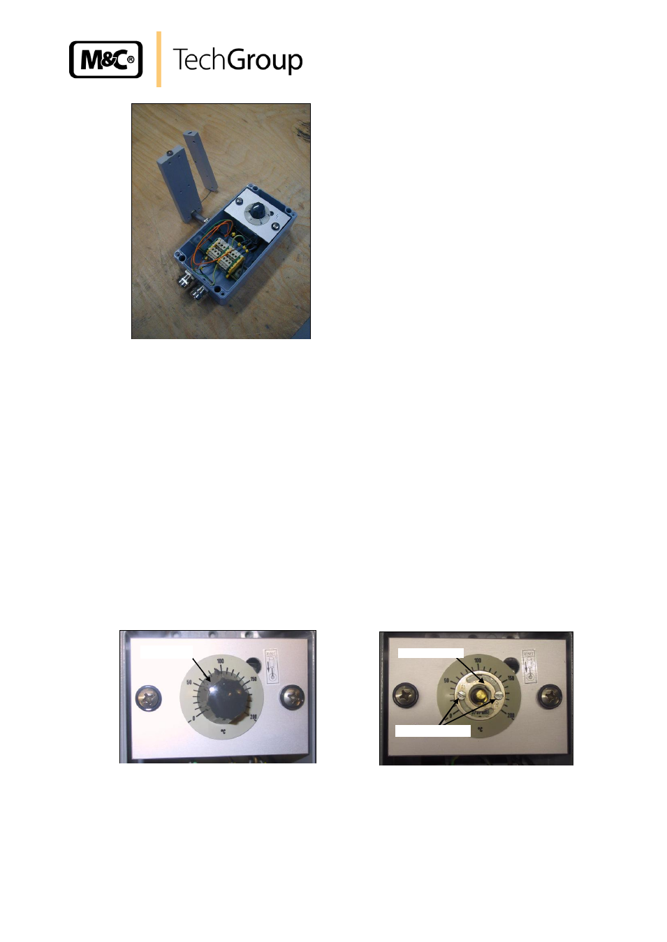
Figure 17 Connection box with heating cartridge and thermostat sensor
Disconnect on the terminal strip the electrical connection lines of the heating cartridge and of
the thermostat.
Tear off the turning knob on the thermostat. Remove both fixing screws being under there (see
figure 18). Remove also the 2 fixing screws of the thermostat receiving plate.
Tear out the heating cartridge through the cable gland “C“.
Tear out the thermostat sensor of the aluminium block and through the cable gland in the op-
posed direction.
Mount the new thermostat and lead the thermostat sensor through the cable gland.
Also lead in the new heating cartridge through the cable gland.
Connect the electrical lines according to terminal connecting plan.
Mount the complete unit on to the probe again.
The thermostat has got a mechanical stop that is limiting the maximum adjustable temperature to be
set by using the turning knob.
When mounting the thermostat, this mechanical stop must be adjusted in such a way that the arrow
on the metal ring shows the desired maximum temperature (standard adjustment 190°C).
Figure 18 Mechanical stop of the thermostat
If you use gas sample probes with temperature sensor (PT100 or thermo element) instead of the
thermostat, you must lead the sensor connection line together with the heating cartridge through the
cable gland. For this purpose, put the connection line into the bead of the sealing ring the two metal
rings.
Mechanical Stop
Fixing Screws
Turning knob