M&C TechGroup DIL-U Data sheet User Manual
Sample dilution system version dil-u, Special features, Application
M&C TechGroup Germany GmbH • Rehhecke 79 • 40885 Ratingen • Germany
[email protected] • www.mc-techgroup.com • Fon +49 2102 935-0 • Fax +49 2102 935-111
5.3
Embracing Challenge
Lowest dilution ratio 1:1
Ambient air as dilution gas possible
Low dilution gas consumption
No influence of barometric pressure
1
Compact design
Gas sample probe SP2000H/...
Incorporated pre heater for dilution gas
Test gas connection at the probe inlet
Completely heated up to 180°C
1
varying process pressure must be taken into
consideration
Special Features
Sample dilution system version DIL-U
consisting of dilution probe SP2000H/DIL-U/P
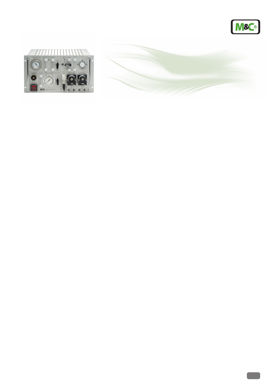
and dilution pump unit DIL-U/A (N)
DIL-U/A(N)
Application
The electrically heated M&C dilution system
DIL-U is applicable for such processes, where
the measuring procedure or the handling of
the process gas requires the dilution of the
sample respectively the component to be
measured in a range of 100:1 up to 1:1.
Typical applications:
•
toxic gases above TLV value
•
explosive gas mixture above LEL
•
adapting the concentration of the sam-
ple components to the measuring range
of the analyser
•
measuring possibility at low sample flow
rates from 1Nl/hr
•
moisture measurement in flue gas with
IR-analyser
The M&C dilution probe (part of this system)
is based on the well tested modular designed
M&C gas sample probe SP2000H. This enables
the user to adapt the probe to nearly every
application, using for example special filter
techniques or special materials.
Description
The M&C dilution system DIL-U consists of the
dilution probe SP2000H/DIL-U/P and the dilu-
tion pump unit DIL-U (A/N).
The dilution unit, including the critical ori-
fices, is integrated in the sample probe outlet,
heated up with the probe to a stable temper-
ature. The incorporated pre heater heats
up the dilution gas to the probe temperature.
Both steps avoid that the temperature of
sample gas decreases under the dew point.
The test gases for the system calibration enter
the sample probe via an integrated valve.
A vacuum pump integrated in the pump unit
DIL-U sucks the required vacuum, which is
necessary for the function of the critical orific-
es. A pressure gauge indicates the function of
the dilution system. The flowmeters indicate
the analyser and bypass flow 1. A flow alarm
is available as well.
For test procedure with zero and span gas a
3 way ball valve and a flowmeter is installed.
Version DIL-U/A is suitable for ambient air as
a dilution gas and version DIL-U/N for bottle
gas. Bottle gas requires a pressure regulator,
a pressure gauge and a flowmeter which can
be installed optional in the pump unit.
If the dew point of the diluted sample is
higher then ambient temperature an option-
al integrated M&C cooler, ECP1000G/SR25,
reduces it to +5 °C.
High dilution ratios cause a very low sam-
ple flow. Therefore it is necessary to use an
additional sample bypass 2 to reduce the
response time. This will be done with the
option DIL-U/B with an additional pump and
flowmeter and the cooler as an option.
The heated M&C sample line(s) 3/4-N/M/H
between the probe and the pump unit can
be controlled via an temperature controller
703, built into the pump unit.
The design of the dilution system DIL-U guar-
antees easy maintenance.
Technical specifications and illustrations are without
obligation, subject to modifications. 12.99/06.06