Figure 14, N o t e – M&C TechGroup SP2000-H320_S2 Operator's manual User Manual
Page 29
29
Gas sampling and gas conditioning technology
2-1.1.4-ME
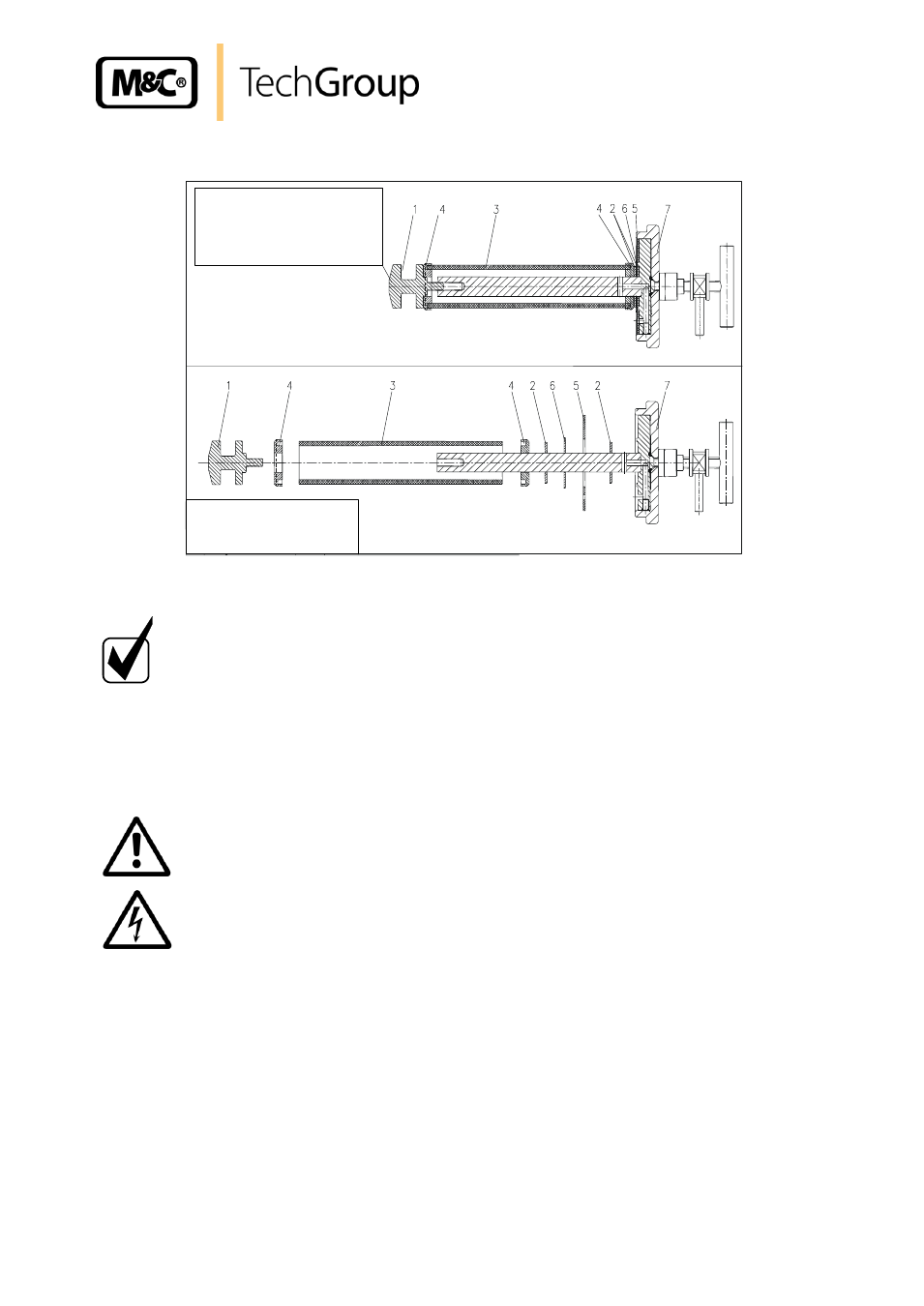
Gas sample probe SP2000-H320/0,1GF with 0,1µ fibre glass filter element
Mounting notice
Screw in kn
urled screw “1” until the filter
element is tightend slightly.
Afterwards screw in the knurled screw “1”
an additional rotation (360°)
1 Filter screw
93S2084
2 Gasket (30)
93S0055
3 Filter element 0,1 µm
90F0125
4 Adaptor ring stainl. Steel
93S0053
5 Gasket (69)
93S0030
6 Fixing disk
93S0034
7 Filter housing lid
93S2086
Figure 14 Mounting notice for probes with fibre glass filter element F-0,1GF 150
N O T E !
For replacement of the pre-filters, remove the complete probe
unit out of the process. The pre-filters can be cleaned mechani-
cally or in the ultrasonic bath according to the degree of con-
tamination and be used again.
16.2 REPLACEMENT OF THE HEATING CARTRIDGE AND THE THERMOSTAT
W A R N I N G !
Prior to works on any electrical parts, the power supply has to
be switched off on all poles! this is also valid for all eventually
connected alarm or control circuits.
Switch the probe free from voltage (Switch off the power supply) and let the probe cool down.
Remove the weather protection cover.