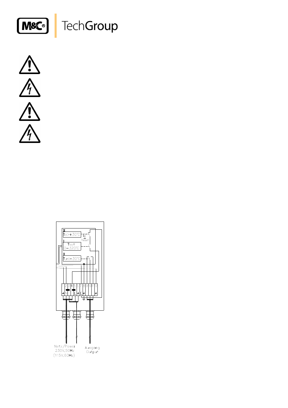
Electrical connection, Figure 9 – M&C TechGroup SP2000-H320_S2 Operator's manual User Manual
Page 20
20
Gas sampling and gas conditioning technology
2-1.1.4-ME
13.4 ELECTRICAL CONNECTION
W A R N I N G !
Wrong supply voltage can destroy the equipment. when con-
necting the device, please ensure that the supply voltage is iden-
tical with the information provided on the type plate!
W A R N I N G !
Attention must be paid to the requirements of IEC 364 (DIN VDE
0100) when setting high-power electrical units with nominal volt-
ages of up to 1000V, together with the associated standards and
stipulations!
A main switch must be provided externally.
The main circuit must be equipped with a fuse corresponding to
the nominal current (over current protection); for electrical de-
tails see technical data.
13.4.1
VERSION SP2000-H320/S WITH INTERNAL CAPILLARY TUBE THERMOSTAT
Remove the lid of the connection box. Inside the lid, you can see the terminal connecting plan.
Insert the mains cable (min. 3 x 1,5 mm
2
, terminal range 6-12mm) through the left cable gland
and connect it to the appropriate terminals.
Insert the signal cable (terminal range 6-12mm) through the right cable gland and connect it to
the appropriate terminals.
Screw lid on again.
Figure 9 Electrical connection SP2000-H320/S with thermostat