Figure 11 – M&C TechGroup SP2000-H320_S2 Operator's manual User Manual
Page 23
23
Gas sampling and gas conditioning technology
2-1.1.4-ME
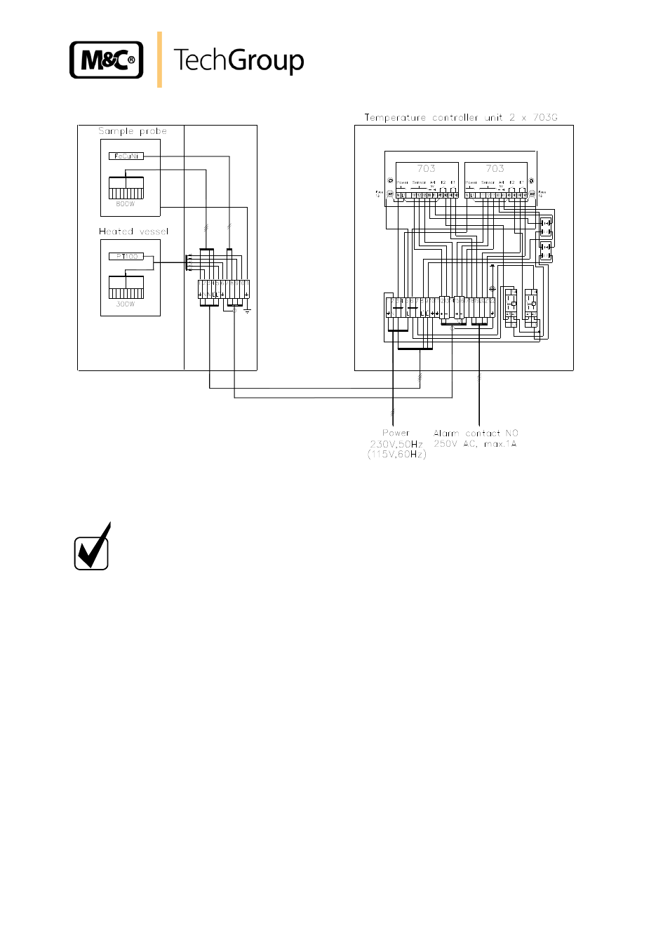
Figure 11 Electrical connection SP2000-H320/S2 with electronic double controller 703G
N O T E !
As sensor line an equalization line has to be provided. The appropriate
thermo equalization terminals are available inside the connection box.
The electrical connection of the temperature controller Type 703G is to be made according the termi-
nal connection plan as shown in figure 11 and being described as follows:
Screw off the housing lid.
Insert the mains cable (min. 3 x 1,5 mm
2
, terminal range 6
– 12mm) through the left cable
gland and connect it to the appropriate terminals.
Insert the cable for the alarm contact (terminal range 6
– 12mm) through the fifth cable gland
and connect it to the appropriate terminals.
In case the temperature controller Type 703G is delivered as separate unit, the probe is to be con-
nected according to figure 11 and as described as follows:
Insert the mains cable for the gas sample probe (min. 3 x 1,5 mm
2
, terminal range 6
– 12mm)
through the second cable gland of the controller and connect it to the appropriate terminals.
Insert the temperature sensor cable (terminal range 6
– 12mm) through the third cable gland
of the controller and connect it to the appropriate terminals.
Screw the housing lid on again.