Toshiba RAS-M13EKCVP-E User Manual
Page 114
– 114 –
No.
Remarks
Procedures
Part name
P.C. board base
P.C. board
CN300
Main P.C. board
CN701
Sub P.C. board
Connector
Ty lap tie
Two claws
Two screws
(PT2F-4X10MS-ZN)
Hook
Sub PCB
base
CN14
CN13
CN02
CN03
CN04
CN05
CN07
CN01
CN10
CN12
CN11
Control board
assembly
%
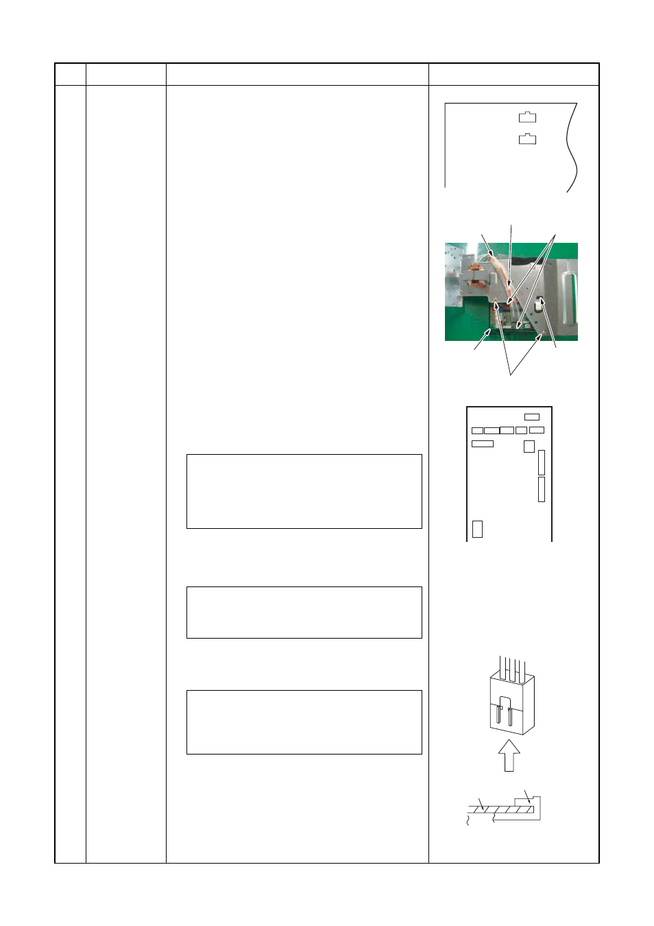
1) Disconnect the leads and connectors connected to
the other parts from the control board assembly.
1) Leads
• 3 leads (black, white, orange) connected to
terminal block.
• Lead connected to compressor : Disconnect
the connector (3P).
• Lead connected to reactor : Disconnect the
two connectors (2P).
2) Connectors (x8)
Main P.C. board
CN300 : Outdoor fan motor (3P: white)*
(See Note)
CN701 : 4-way valve (2P: yellow)*
Sub P.C. board
CN01 : TE sensor (2P: white)*
CN11 : PMW (6P: white)
CN12 : PMV (6P: red)
CN04 : TS sensor (3P: white)*
CN02 : TD sensor (3P: white)*
CN03 : TO sensor (2P: white)
CN05 : TGa sensor (3P: yellow)
CN14 : TGb sensor (3P: red)
CN10 : Case thermo (2P: blue)*
CN07 : Lead for communication
CN13 : Lead for AC power supply
Note :
These connectors have a disconnect preven-
tion mechanism: as such, the lock on their
housing must be released before they are
disconnected.
2) Remove the control board assembly from the
P.C. board base. (Remove the heat sink and
control board assembly while keeping them
screwed together.)
Note :
Disengage the four claws of the P.C. board
base, hold the heat sink, and lift to remove it.
3) Remove the two fixing screws used to secure
the heat sink and control board assembly.
4) Mount the new control board assembly.
Note :
When mounting the new control board assem-
bly, ensure that the P.C. board is inserted
properly into the P.C. board support groove.
5) Disconnect the connectors.
6) Remove the two screws (PT2F-4X10MS-ZN),
then remove the Sub P.C. board base while
disengaging the claws from the square holes.
7) Disengage the two claws of the Sub P.C. board
base and remove the Sub P.C. board.
CN300, CN701, CN600 and
CN603 are connectors with
locking mechanisms: as such,
to disconnect them, they must
be pressed in the direction of the
arrow while pulling them out.