Texas Instruments TMS380C26 User Manual
Page 18
TMS380C26
NETWORK COMMPROCESSOR
SPWS010A–APRIL 1992–REVISED MARCH 1993
POST OFFICE BOX 1443
•
HOUSTON, TEXAS
77251–1443
18
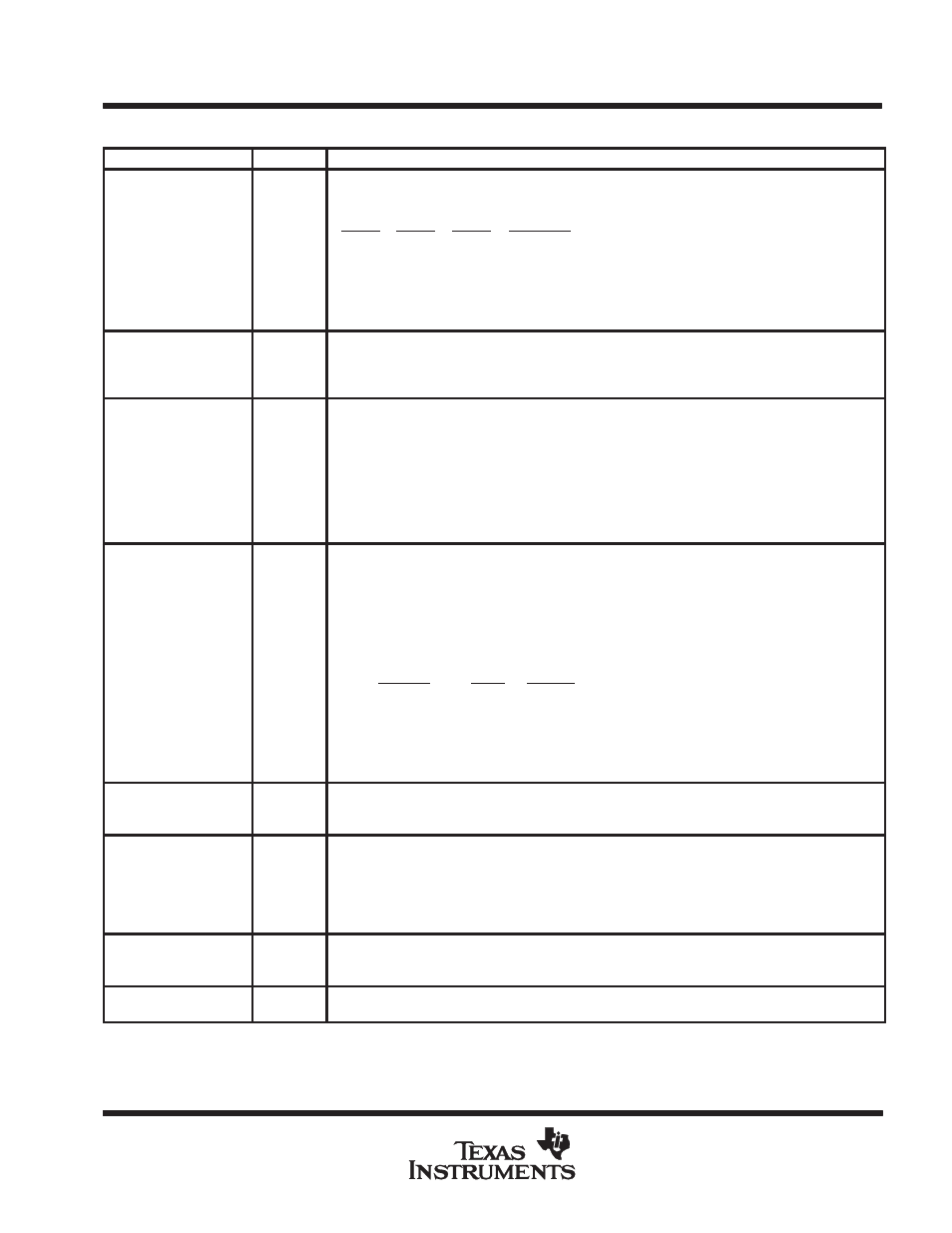
Terminal Functions (continued)
PIN NAME
NO.
I/O
DESCRIPTION
TEST 0
TEST 1
TEST 2
79
78
77
IN
IN
IN
Network Select inputs. These pins are used to select the network speed and type to be used by the
TMS380C26. These inputs should only be changed during adapter reset.
TEST0
TEST1
TEST2
Description
L
L
H
Reserved
L
H
H
16 Mbps token ring
H
L
H
Ethernet (802.3/Blue Book)
H
H
H
4 Mbps token ring
X
X
0
Reserved
TEST3
TEST4
TEST5
76
75
74
IN
IN
IN
Test Pin Inputs. These pins should be left unconnected (see Note 1).
Module-in-Place test mode is achieved by tying TEST 3 and TEST 4 pins to ground. In this mode,
all TMS380C26 output pins are high impedance. Internal pullups on all TMS380C26 inputs will be
disabled (except TEST3-TEST5 pins).
XFAIL
80
IN
External Fail-to-Match signal. An enhanced address copy option (EACO) device uses this signal to
indicate to the TMS380C26 that it should not copy the frame nor set the ARI/FCI in bits in a token
ring frame due to an external address match.The ARI/FCI bits in a token ring frame may be set due
to an internal address matched frame. If an enhanced address copy option (EACO) device is NOT
used, then this pin must be left unconnected. This pin is ignored when CAF mode is enabled.
See table given below in XMATCH pin description (see Note 1).
H = No address match by external address checker.
L
= External address checker armed state.
XMATCH
81
IN
External Match signal. An enhanced address copy option (EACO) device uses this signal to indicate
to the TMS380C26 to copy the frame and set the ARI/FCI bits in a token ring frame. If an enhanced
address copy option (EACO) device is NOT used, then this pin must be left unconnected. This pin
is ignored when CAF mode is enabled (see Note 1).
H = Address match recognized by external address checker.
L
= External address checker armed state.
XMATCH
XFAIL
Function
0
0
Armed (Processing frame data).
0
1
Do NOT externally match the frame. (XFAIL takes precedence)
1
0
COPY the frame.
1
1
Do NOT externally match the frame. (XFAIL takes precedence)
HI-Z
HI-Z
Reset state (adapter not initialized).
VDDL
18
34
100
IN
Positive supply voltage for digital logic. All VDD pins must be attached to the common system power
supply plane.
VDD1
VDD2
VDD3
VDD4
VDD5
VDD6
82
109
124
16
50
66
IN
Positive supply voltage for output buffers. All VDD pins must be attached to the common system
power supply plane.
VSSC
20
65
116
IN
Ground reference for output buffers (clean ground). All VSS pins must be attached to the common
system ground plane.
VSSI
41
117
IN
Ground reference for input buffers. All VSS pins must be attached to the common system ground
plane.
NOTE 1: Pin has an internal pullup device to maintain a high voltage level when left unconnected (no etch or loads).