RAD Data comm ASMI-450 User Manual
Page 34
Installation
2-4
ASMi-450 Installation and Operation Manual
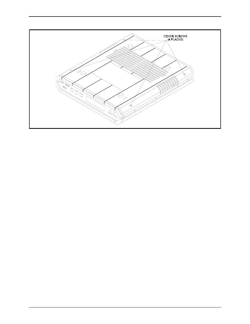
Figure 2-1. Identification of Cover Screws
Jumper and Switch
Location and
Functions
The ASMi-450 consists of a main board and a user's port interface board. The
jumpers and switches located on the ASMi-450 main board are identified in
figure 2-2. Their functions are described below.
In addition to the jumpers listed below, the ASMi-450 has additional jumpers,
that are set by the manufacturer and must not be changed by you.
Note
Figure 2-2 also indicates the location of the 1A protection fuses, F1 and F2,
used to protect the line side of the isolation transformers of the HDSL line.
The type of user's port interface board depends on the interface installed on your
ASMi-450. None of the user's port interface boards offered with the ASMi-450
includes user-selectable jumpers.
Switch S1
The ASMi-450 is delivered with a set of default parameters that allow the user
to start the configuration activities from a known state. These parameters are
stored in its program EPROM, and therefore cannot be modified. By
configuring the ASMi-450, the user specifies custom parameter values; these
parameter values are stored in the ASMi-450 data base (located in non-volatile
memory), and are automatically loaded each time the ASMi-450 is powered up.
Note
If during the power-up self-test, it is found that the user's configuration has
been corrupted, the ASMi-450 will automatically reload the default parameters
from its EPROM.