Step procedure (continued) – Paradyne BitStorm IP DSLAM 1900 User Manual
Page 68
2. BitStorm 1900 Installation and Testing
2-52
BitStorm 1900 Installation and Maintenance Guide
1900-A2-GN20-00
Step
Procedure
(continued)
NOTE: The redundant power supply sources connect to two pairs of wires on
the BitStorm 1900’s power harness and are electrically the same.
5.)
Route the other end of the DC power harness to the DC power
connector on the backplane of the BitStorm 1900 modem shelf.
The connector only fits one way.
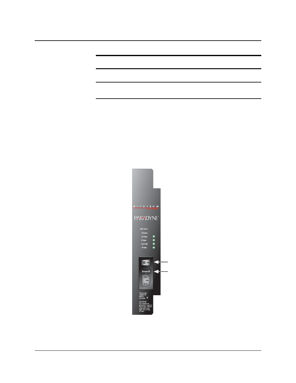
6.)
For an AC power supply, connect the power cord to the IEC
terminal connection on the front panel.
Figure 2-9: Typical Power Connection to 260W AC Power Source
7.)
Route the other end of the cord to a grounded socket.
8.)
Re-seat the power, modem, and MIU Shelf processor into their
shelf backplane connectors.
ON/OFF
FUSE
3A, 250V AC
02-17181
- ACCULINK 336x E1 (168 pages)
- 6211 (72 pages)
- 6301 (142 pages)
- 3825-A2-GX40-00 (1 page)
- STORMPORT 1020 (2 pages)
- 3911 (280 pages)
- 8314 (136 pages)
- T1 T1 Access Mux 926x (326 pages)
- COMSPHERE 3610 (81 pages)
- 8779 (182 pages)
- COMSPHERE 3616 (135 pages)
- 6212 (102 pages)
- 3830 (125 pages)
- IP DSLAM GranDSLAM 4200 (72 pages)
- ACCULINK 317x E1 (167 pages)
- 6302 (126 pages)
- 7612 SNMP DSU (126 pages)
- and 3165-A4 (316 pages)
- Jetstream CPX-1000 (160 pages)
- IP Broadband Loop Carrier 4000E (20 pages)
- 3164 (296 pages)
- 39xx Series (1 page)
- Hotwire ATM Line Cards 8335 (132 pages)
- 12-Port VoSHDSL Access Multiplexer SAM2000V-12 (10 pages)
- ACCULINK 7800-D1-999 (11 pages)
- COMSPHERE 6700 SERIES (57 pages)
- 3160-A3 (298 pages)
- 1810 (31 pages)
- 12-Port T1 Access Multiplexer TAM1500-12 (8 pages)
- COMSPHERE 3000 (131 pages)
- 8785 (12 pages)
- BitStorm 2600 IP DSLAM (58 pages)
- 3825PLUS (107 pages)
- 6210 (46 pages)
- 4300 (22 pages)
- Fan Tray Assembly 8820-S3-900 (6 pages)
- OpenLane SLM 5.5 (112 pages)
- 8510 RADSL (108 pages)
- Adapter Bracket (1 page)
- 9550 DS3 (20 pages)
- Single T1 Network Access Module (NAM) 9161-A2-GN10-40 (15 pages)
- 5216 (20 pages)
- 9126-II (470 pages)
- COMSPHERE 6700-A2-GB22-00 (60 pages)
- 7915-A1 E1 SDSL (1 page)