Step procedure (continued) – Paradyne BitStorm IP DSLAM 1900 User Manual
Page 67
2. BitStorm 1900 Installation and Testing
1900-A2-GN20-00
BitStorm 1900 Installation and Maintenance Guide
2-51
Step
Procedure
(continued)
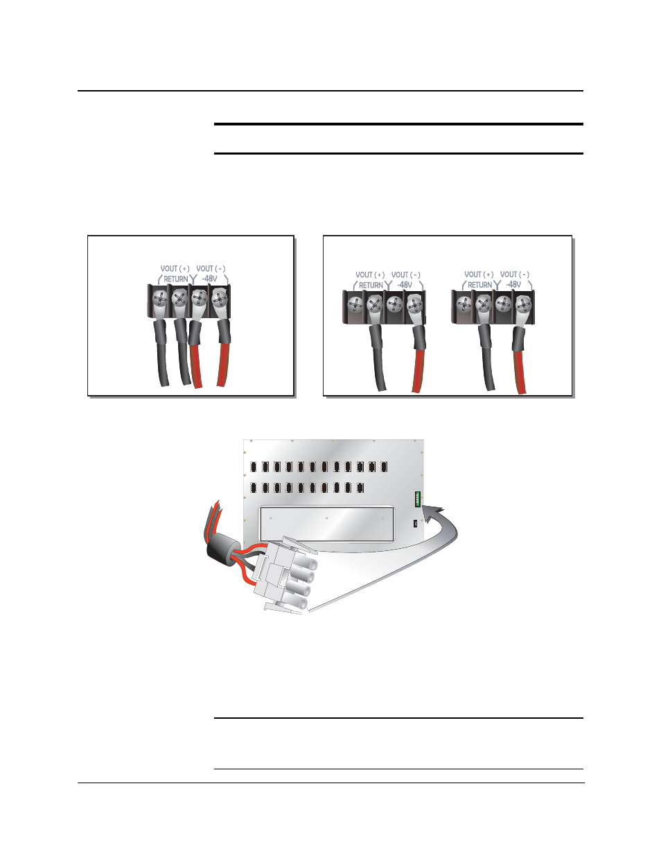
Figure 2-8: Typical DC Power Harness Connection to -48 V DC (260W) Power Source
4.)
For a -48 V DC power source, connect the red power lead to the
Negative (-) terminal connection and the black power lead to the
Positive (+) terminal connection as seen in Figure 2-8, "Typical DC
Power Harness Connection to -48 V DC (260W) Power Source,"
on page 51.
NOTE: If using a -48 V DC power supply, use an appropriate volt-ohm meter to
test and verify that the red power feed at the shelf is the -48 V DC
supply. The meter should read between -46 and -56 V DC.
RED LEAD
-48V dc
Negative ( - )
Terminal
BLACK LEAD
V dc Return
Positive ( + )
Terminal
BLACK LEAD
V dc Return
Positive ( + )
Terminal
RED LEAD
-48V dc
Negative ( - )
Terminal
Power Supply #1
Power Supply #2
Single Power Source
Rundant Power Source
02-17180
- ACCULINK 336x E1 (168 pages)
- 6211 (72 pages)
- 6301 (142 pages)
- 3825-A2-GX40-00 (1 page)
- STORMPORT 1020 (2 pages)
- 3911 (280 pages)
- 8314 (136 pages)
- T1 T1 Access Mux 926x (326 pages)
- COMSPHERE 3610 (81 pages)
- 8779 (182 pages)
- COMSPHERE 3616 (135 pages)
- 6212 (102 pages)
- 3830 (125 pages)
- IP DSLAM GranDSLAM 4200 (72 pages)
- ACCULINK 317x E1 (167 pages)
- 6302 (126 pages)
- 7612 SNMP DSU (126 pages)
- and 3165-A4 (316 pages)
- Jetstream CPX-1000 (160 pages)
- IP Broadband Loop Carrier 4000E (20 pages)
- 3164 (296 pages)
- 39xx Series (1 page)
- Hotwire ATM Line Cards 8335 (132 pages)
- 12-Port VoSHDSL Access Multiplexer SAM2000V-12 (10 pages)
- ACCULINK 7800-D1-999 (11 pages)
- COMSPHERE 6700 SERIES (57 pages)
- 3160-A3 (298 pages)
- 1810 (31 pages)
- 12-Port T1 Access Multiplexer TAM1500-12 (8 pages)
- COMSPHERE 3000 (131 pages)
- 8785 (12 pages)
- BitStorm 2600 IP DSLAM (58 pages)
- 3825PLUS (107 pages)
- 6210 (46 pages)
- 4300 (22 pages)
- Fan Tray Assembly 8820-S3-900 (6 pages)
- OpenLane SLM 5.5 (112 pages)
- 8510 RADSL (108 pages)
- Adapter Bracket (1 page)
- 9550 DS3 (20 pages)
- Single T1 Network Access Module (NAM) 9161-A2-GN10-40 (15 pages)
- 5216 (20 pages)
- 9126-II (470 pages)
- COMSPHERE 6700-A2-GB22-00 (60 pages)
- 7915-A1 E1 SDSL (1 page)