Kohler Command Pro CV980 User Manual
Page 96
Section 9
Inspection and Reconditioning
9.4
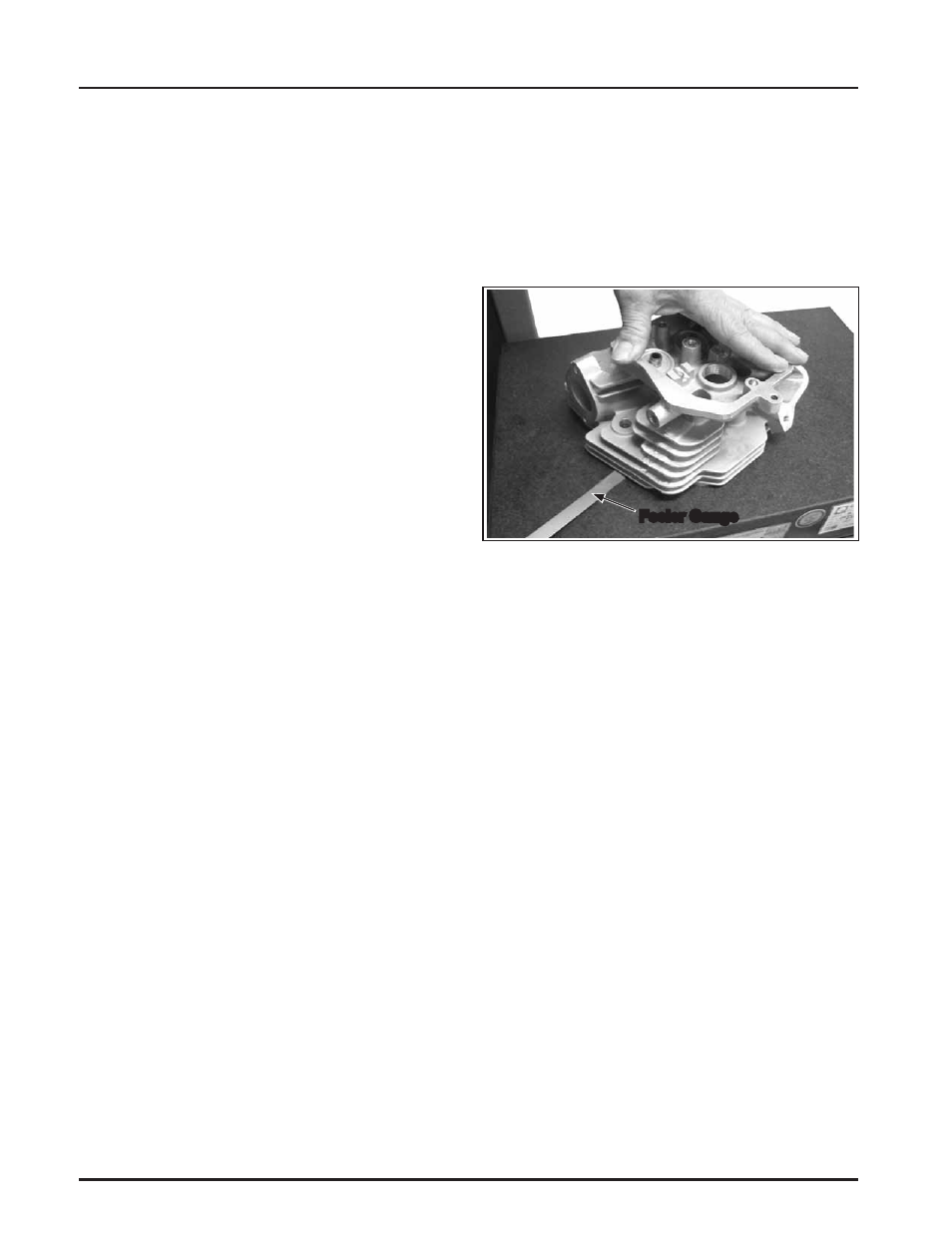
Feeler Gauge
2. Use an inside micrometer, telescoping gauge, or
bore gauge and measure the cylinder bore. Take
the measurement approximately 63.5 mm
(2.5 in.) below the top of the bore and
perpendicular to the piston pin.
ȱ řǯȱ ȬȬȱȱȱȱěȱ ȱ
the bore diameter and the piston diameter (step 2
minus step 1).
Flywheel
Inspection
ȱȱĚ¢ ȱȱȱȱȱĚ¢ ȱ
¢ ¢ȱȱǯȱȱȱĚ¢ ȱȱȱȱ
ǯȱȱȱĚ¢ ǰȱȱĞǰȱȱ
ȱ¢ȱȱĚ¢ ȱ¢ȱȱȱȱȱ¢ ¢ȱȱ
damaged.
ȱȱȱȱȱȱȱǯȱ
ȱ
does not provide the ring gear as a serviceable part.
ȱȱĚ¢ ȱȱȱȱȱȱǯ
Cylinder Head and Valves
Inspection and Service
ĞȱǰȱȱȱĚȱȱȱ¢ȱȱ
and the corresponding top surface of the crankcase,
using a surface plate or piece of glass and feeler gauge
as shown in Figure 9-5. The maximum allowable out
ȱĚȱ 0.076 mm (0.003 in.).
Figure 9-5. Checking Cylinder Head Flatness.
Carefully inspect the valve mechanism parts. Inspect
the valve springs and related hardware for excessive
wear or distortion. Check the valves and valve seat
ȱȱȱȱȱȱȱĴǰȱǰȱ
or distortion. Check clearance of the valve stems
in the guides. See Figure 9-6 for valve details and
ęǯ