Kohler Command Pro CV980 User Manual
Page 38
5.10
Section 5
Fuel System and Governor
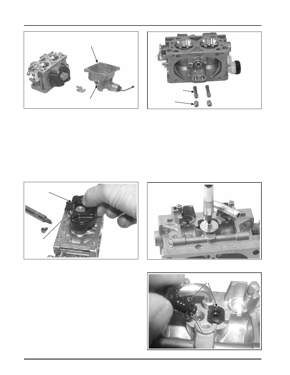
Figure 5-18. Fuel Bowl Removed From Carburetor.
DZȱ ȱ¢ȱȱȱȱ ȱ
is not necessary unless the Fuel
Solenoid Kit, or Fuel Bowl Kit (obtained
separately), will also be installed.
ȱȱŘǯȱ ȱȱĚȱȱ ȱȱĞȱȱȱȱ
ĚǰȱǰȱȱȱǯȱȱȱśȬŗşǯȱ
Discard all the old parts. The seat for the inlet
needle is not serviceable, and should not be
removed.
Figure 5-19. Removing Float and Inlet Needle.
ȱ řǯȱ ȱȱȱ£ȱĚȱ ǰȱȱ
carefully remove the two main jets from the
carburetor. Note and mark the jets by location for
ȱǯȱȱȱȱ¢ȱȱ£Ȧȱ
ęǯȱĞȱȱȱȱȱǰȱȱȱ
££ȱȱȱȱȱȱȱĴȱ
ȱȱȱ ǯȱȱȱȦȱ
of the nozzles. The end with the two raised
ȱȱȱȦ ȱȱȱȱ
main jets. Save the parts for cleaning and reuse.
ȱȱśȬŘŖǯ
Figure 5-20. Main Jets and Nozzles Removed.
ȱ Śǯȱ ȱȱ ȱȱȱĚȱ ȱȱ
ground lead (if equipped), from the top of the
Dzȱȱ¢ȱȱǻĞǼȱȱȱ ȱ
ȱǯȱȱ ȱȱ¢ȱȱ£Ȧȱęǰȱ
mark or tag for proper reassembly. Note the small
ȬȱȱȱĴȱȱȱǯȱȱȱśȬŘŗȱ
ȱśȬŘŘǯȱȱȱȱȱȱȱȱ
a Jet Kit is also being installed. Clean the slow
jets using compressed air. Do not use wire or
carburetor cleaner.
Figure 5-21. Removing Screw and Washer.
Figure 5-22. Slow Jets and O-Ring Detail.
Float
Inlet
Needle
Fuel Bowl
Bowl Drain Screw
Main Jets
Main Nozzles
Slow (Idle Fuel) Jets
O-Ring