Kohler Command Pro CV980 User Manual
Page 55
7.5
Section 7
Electrical System and Components
7
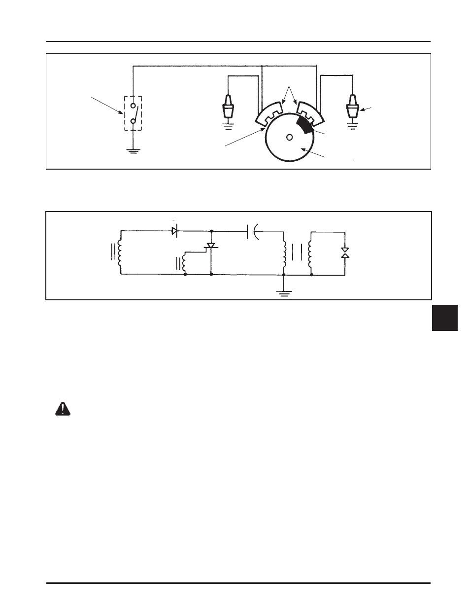
Kill Switch or
‘‘Off’’ Position of
Key Switch
Ignition
Modules
Spark Plug
Magnet
Flywheel
(0.28/0.33 mm)
0.011/0.013 in. Air Gap
L1
D1
C1
T1
P
S
Spark Plug
L2
SCS
Figure 7-5. Capacitive Discharge (CD) Ignition Module Schematic.
Figure 7-4. Capacitive Discharge Fixed Timing Ignition System.
ȱȱȱȱȱȱȱ¢ȱȱȱȱȱĚ¢ ȱȱȱȱȱȱȱȱ
dead center.
Troubleshooting CD Ignition Systems
ȱȱȱ¢ȱȱȱȱȱȱ
ȱȱȱȱȱȱǯȱȱȱ¢ȱ
Ȧȱȱȱǰȱȱȱ
ȱȱȱȱ¢ȱȱǯȱ
ȱ¢ȱȱ¢ȱȱȱȱ
ȱ ǰȱȱȱ ȱȱ
information is provided to help you get to the root of
ȱȱǯ
CAUTION: High-Energy Electric Spark!
ȱȱȱ¢ȱȱȱȬ¢ȱȱ
ǰȱȱȱȱȱȱǰȱȱȱȱȱ
¢ȱȱǯȱȱȱȱȱȱȱȱ ȱȱ
ȱȱȱǯȱ ¢ȱȱȱȱȱȱ
ȱȱȱȱǯ
ȱȱȱȱȱĞȱȱȱ
ȱǯȱȱȱȱȱǰȱ
ȱȱ¡ȱ ǯȱȱȱȱȬȱ
wires are connected, including the spark plug leads.
ȱȱȱȱȱęȱ¢ǯȱȱ
sure the ignition switch is in the run position.
DZȱ ȱȱȱ¢ȱȱȱȱ
excessive load on the kill lead. If a customer
complains of hard starting, low power,
ȱęȱȱǰȱȱ¢ȱȱȱȱ
excessive draw on the kill circuit. Perform the
appropriate test procedure.
Test Procedure for Standard (Fixed Timing) CD
Ignition System
ȱȱ¢ȱȱȱȱ ȱȱȱ
ignition system.
ȱ ŗǯȱ ȱȱȱȱ ȱȱ ȱ
harnesses from the engine and equipment are
ǯȱȱȱȱȱȱȱ
ȱȱȱȱȱȱǯȱȱ
the connectors and position or insulate the kill
lead terminal so it cannot touch ground. Try to
start the engine to verify whether the reported
ȱȱȱǯ
DZȱ ȱȱȱȱȱȱȱ¢ȱȱȱ
testing, you may need to ground the kill lead
to shut it down. Because you have interrupted
the kill circuit, it may not stop using the
switch.