Kohler Command Pro CV980 User Manual
Page 34
5.6
Section 5
Fuel System and Governor
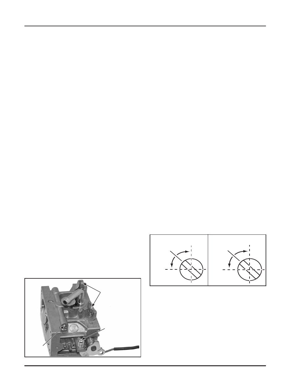
Lean
Rich
Adjust to
Midpoint
Lean
Rich
Adjust to
Midpoint
Left Side
Right Side
Carburetor Adjustments
Adjustment
DZȱ ȱȱȱȱȱ¢ȱ
Ğȱȱȱȱ ȱǯ
The carburetor is designed to deliver the correct
fuel-to-air mixture to the engine under all operating
conditions. The main fuel jet is calibrated at the
factory and is not adjustable*. The idle fuel adjusting
needle is also set at the factory and normally does not
need adjustment.
ȘDZȱ ȱȱȱȱȱ
¡¢ȱŗśŖŖȱȱǻśŖŖŖȱĞǯǼȱ¢ȱ
require a special ‘‘high altitude’’ main
ǯȱȱȱȁȁȱȱȂȂȱ
later in this section.
If, however, the engine is hard-starting or does not
operate properly, it may be necessary to adjust or
service the carburetor.
Low Idle Speed (RPM) Adjustment
1. ȱȱȱǻǼȱĴDZȱȱȱĴȱ
control in the “idleȄȱȱȃslowȄȱǯȱȱȱ
low idle speed approximately 300 RPM less than
ȱȱȱęȱ ȱȱǰȱ
by turning the low idle speed adjusting screw
in or out. Check the speed using a tachometer.
IMPORTANT: The Governed Idle Speed
ȱȱ ȱ¢ȱĴȱȱȱ
Low Idle Speed.
ȘDZȱ ȱȱ ȱȱȱȱȱ
the application. Refer to the equipment
manufacturer’s recommendations.
The low idle speed for basic engines is
1200 RPM. To ensure best results when
Ĵȱȱ ȱȱȱǰȱȱ ȱ
idle speed should be 1200 RPM (± 75
RPM).
Figure 5-5. Carburetor Adjustment Locations.
Low Idle Fuel Adjustment
DZȱ ȱ ȱȱę¡ȱ ȱȱȱȱ
caps on the two idle fuel adjusting needles.
Step 3 can only be performed within the
ȱ ȱ¢ȱȱǯȱȱȱĴȱȱ
remove the limiter caps.
ȱ ŗǯȱ ȱȱȱȱȱȱȱĴȱȱśȱȱŗŖȱ
minutes to warm up. The engine must be warm
ȱȱȱŘǰȱřǰȱȱŚǯ
ȱŘǯȱ ȱȱĴȱȱȱȱȃȄȱȱȃ Ȅȱ
ǯȱȱȱ ȱȱȱȱŗŘŖŖȱ
ǯȱ ȱȱȃȱȱ ȱȱȱ
ǻǼȄȱǯ
3.ȱ ȱȱȱǻǼȱĴDZ Place the
ĴȱȱȱȃȄȱȱȃ Ȅȱǯ
a. Turn one of the low idle fuel adjusting
needles out (counterclockwise) from the
¢ȱĴȱȱȱȱȱ
decreases (rich). Note the position of the
needle. Now turn the adjusting needle in
(clockwise). The engine speed may increase,
then it will decrease as the needle is turned
in (lean). Note the position of the needle. Set
the adjusting needle midway between the
ȱȱȱĴǯȱȱȱśȬŜǯ
b. Repeat the procedure on the other
low idle adjustment needle.
ȱ Śǯȱ Ȧȱȱ ȱȱȱǻǼǰȱȱȱ
ęȱĴǯ
Figure 5-6. Optimum Low Idle Fuel Settings.
Low Idle
Speed
(RPM)
Adjustment
Screw
Low Idle Fuel
Adjustments
(With Limiters)
Bowl
Vent