Kohler Command Pro CV980 User Manual
Page 86
8.10
Section 8
Disassembly
Remove Valve Covers
1. Remove the screw and grommet securing each
valve cover.
2. Remove the valve cover and gasket from each
cylinder head. Note the locations of individual
ȱȱȱ¢ȱȱěǯȱȱȱŞȬřŞǯ
Figure 8-38. Removing Valve Covers.
Remove Cylinder Heads and Hydraulic
Lifters
ȱ ŗǯȱ ȱȱȱȱ ȱȱȱěȱȱ
rocker arm adjusting nuts.
2. Remove the pipe plug from the cylinder head to
access the screw in the center location. See Figure
ŞȬřşǯ
Figure 8-39. Removing Pipe Plug.
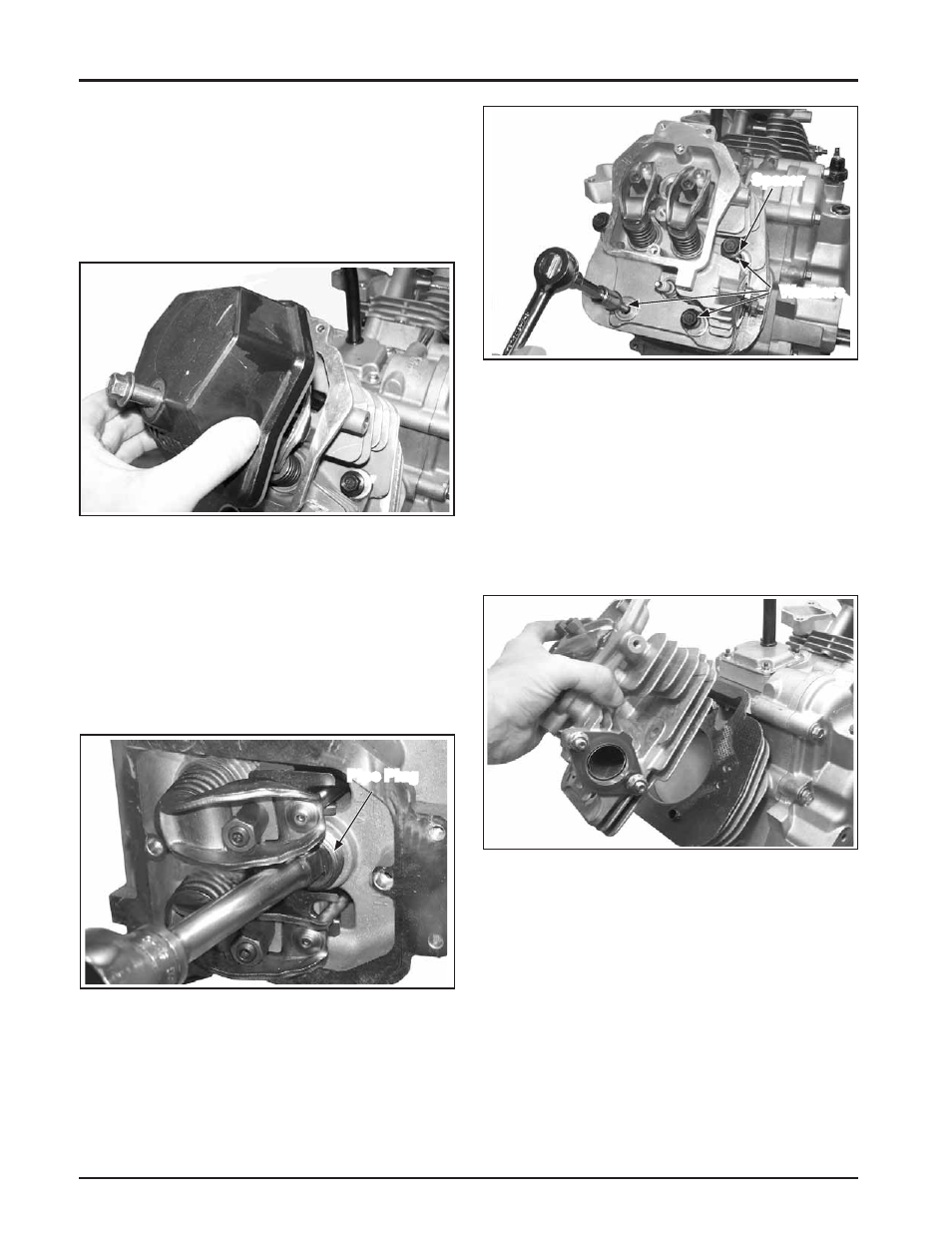
ȱ řǯȱ ȱȱęȱ¡ȱĚȱ ȱȱȱ
cylinder head. Note the locations of washers and
ȱǯȱȱȱŞȬŚŖǯ
Figure 8-40. Removing Cylinder Head Fasteners.
3. Mark the position of the push rods as either
ȱȱ¡ȱȱ¢ȱŗȱȱŘǯȱȱȱ
rods should always be reinstalled in the same
positions.
4. Carefully remove the push rods, cylinder head,
ȱȱǯȱȱȱŞȬŚŗǯ
5. Repeat the procedure for the other cylinder head.
Figure 8-41. Removing Cylinder Head Assembly.
ȱ Ŝǯȱ ȱȱĞȱȱȱĞȱǯȱȱȱ
¢ȱĞȱǯȱȱȱȱȱȱȱ
ȱĞǯȱȱȱĞȱ¢ȱǰȱȱ
either intake or exhaust and cylinder 1 or 2.
¢ȱĞȱȱ ¢ȱȱȱȱ
ȱȱǯȱȱȱŞȬŚŘȱȱŞȬŚřǯ
DZȱ ȱ¡ȱĞȱȱȱȱȱ
ȱĞȱȱȱȱȱ ȱȱ
ȱĞȱȱȱȱȱȱȱ
of the engine. The cylinder head number
is embossed on the outside of each
¢ȱǯȱȱȱŞȬŚřǯ
Pipe Plug
Spacer
Washers