Kohler Command Pro CV980 User Manual
Page 103
Section 9
Inspection and Reconditioning
9
9.11
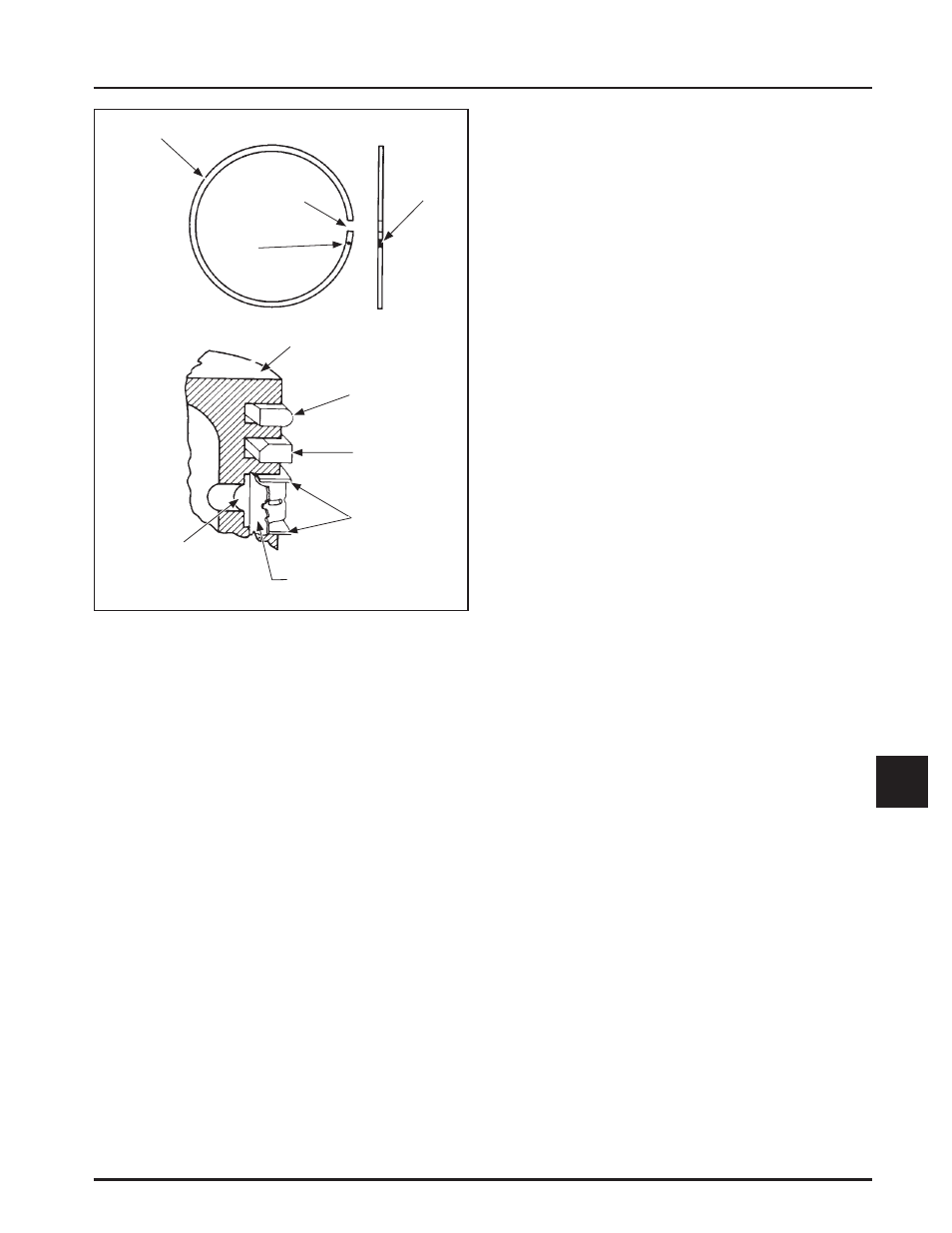
Figure 9-12. Piston Ring Installation.
ȱ ŗǯȱ ȱȱȱǻĴȱ ǼDZȱȱȱ
expander and then the rails. Make sure the ends
of the expander are not overlapped.
2. Middle Compression Ring (Center Groove):
Install the center ring using a piston ring
ȱǯȱȱȱȱȃęȄȱ
mark is up or the dykem stripe (if contained) is to
ȱĞȱȱȱȱǯ
3. Top Compression Ring (Top Groove): Install the
top ring using a piston ring expander. Make sure
ȱȃęȄȱȱȱȱȱȱ¢ȱ
ȱǻȱǼǰȱȱȱȱĞȱȱȱȱǯ
Connecting Rods
ěǰȱȬȱȱȱȱȱȱȱ
engines.
Inspection and Service
Check the bearing area (big end) for excessive wear,
score marks, running and side clearances (refer to
ȱŗǰȱȃęǰȱǰȱȱȱ
ȱȄǼǯȱȱȱȱȱȱȱȱȱ
excessively worn.
Service replacement connecting rods are available in
STD crankpin size and 0.25 mm (0.010 in.) undersize.
Always refer to the appropriate parts information to
ensure that correct replacements are used.
Hydraulic Lifters
Inspection
ȱȱȱȱȱȱ¢ȱĞȱȱ ȱ
ȱǯȱȱȱĞȱȱȱȱǰȱ¢ȱȱ
ȱȱȱ
ȱȱ25 357 14-S to the
ȱȱȱ ȱĞȱȱȱȱǯ
“Bleeding” the Lifters
To prevent a possible bent push rod or broken rocker
ǰȱȱȱȱȱȃȄȱ¢ȱ¡ȱȱȱȱȱ
Ğȱȱ¢ȱȱǯ
1. Cut a 50-75 mm (2-3 in.) piece from the end of an
old push rod and chuck it in a drill press.
2. Lay a rag or shop towel on the table of the drill
ȱȱȱȱĞǰȱȱȱǰȱȱȱ
towel.
3. Lower the chucked push rod until it contacts the
ȱȱȱĞǯȱ ¢ȱȃȄȱȱȱ
two or three times to force the oil out of the feed
ȱȱȱȱȱȱĞǯ
Governor Gear Assembly
Inspection
The governor gear is located within the crankcase.
Inspect the governor gear teeth. Replace the gear if it
is worn, chipped, or if any teeth are missing. Inspect
the governor weights. They should move freely in the
governor gear.
Disassembly
The governor gear must be replaced once it is
removed from the crankcase.
DZȱ ȱȱȱȱȱȱȱĞȱ¢ȱ
small molded tabs in the gear. When the
ȱȱȱȱȱĞȱȱȱȱ
destroyed and the gear must be replaced.
Therefore, remove the gear only if absolutely
necessary.
Piston Ring
End Gap
,GHQWL¿FDWLRQ
Mark
Piston
Top
Compression
Ring
Center
Compression
Ring
Rails
Expander
Oil Control Ring
(Three-piece)
Dykem
Stripe