Kohler Command Pro CV980 User Manual
Page 39
5.11
Section 5
Fuel System and Governor
5
śǯȱ ȱȱȱȱǻǼȱȱ ȱ
and spring from the carburetor. Discard the parts.
DZȱ ȱȱȱ ȱȱȱ
appropriate cleaning and installation
of the parts in the overhaul kit. Further
disassembly is not necessary. The
ĴȱĞȱ¢ǰȱȱȱǰȱ
idle fuel adjustment screws with limiter,
and carburetor body, are non-serviceable
items and should not be removed. The
ȱĞȱ¢ȱȱǰȱ
however it should not be removed
unless a Choke Repair Kit will be
installed.
ȱ Ŝǯȱ ȱȱȱ¢ǰȱȱǰȱȱǰȱ
seats, etc. using a good commercially available
carburetor solvent. Keep away from plastic or
rubber parts if non-compatible. Use clean, dry
compressed air to blow out the internal channels
and ports. Do not use metal tools or wire to
ȱęȱȱǯȱȱȱ¢ȱ
check the carburetor for cracks, wear, or damage.
Inspect the fuel inlet seat for wear or damage.
Check the spring loaded choke plate to make sure
ȱȱ¢ȱȱȱĞǯ
7. Clean the carburetor fuel bowl as required.
8. Install the two main nozzles into the towers
of the carburetor body. The end of the main
nozzles with the two raised shoulders should
ȱȦ ȱǻȱȱȱȱǼǯȱȱ
ȱȱ££ȱȱ¢ȱĴǯȱ
Carefully install the main jets into the towers
of the carburetor body on the appropriate side,
ȱęȱ ȱȱ ȱǯȱȱ
ȱśȬŘřǯ
Figure 5-23. Installing Main Nozzles and Main Jets.
ȱ şǯȱ ȱȱȱȬȱȱȱĴȱȱȱ
ȱȱȱ ǰȱȱȱȱǯȱȱ
and insert the two slow jets into the top of the
ǯȱȱȱśȬŘŘǯȱ
ȱŗŖǯȱ ȱȱǰȱĚȱȱ ȱȱȱ
ȱȱȱ ǰȱĴȱȱȱ
lead if originally secured by the screw.
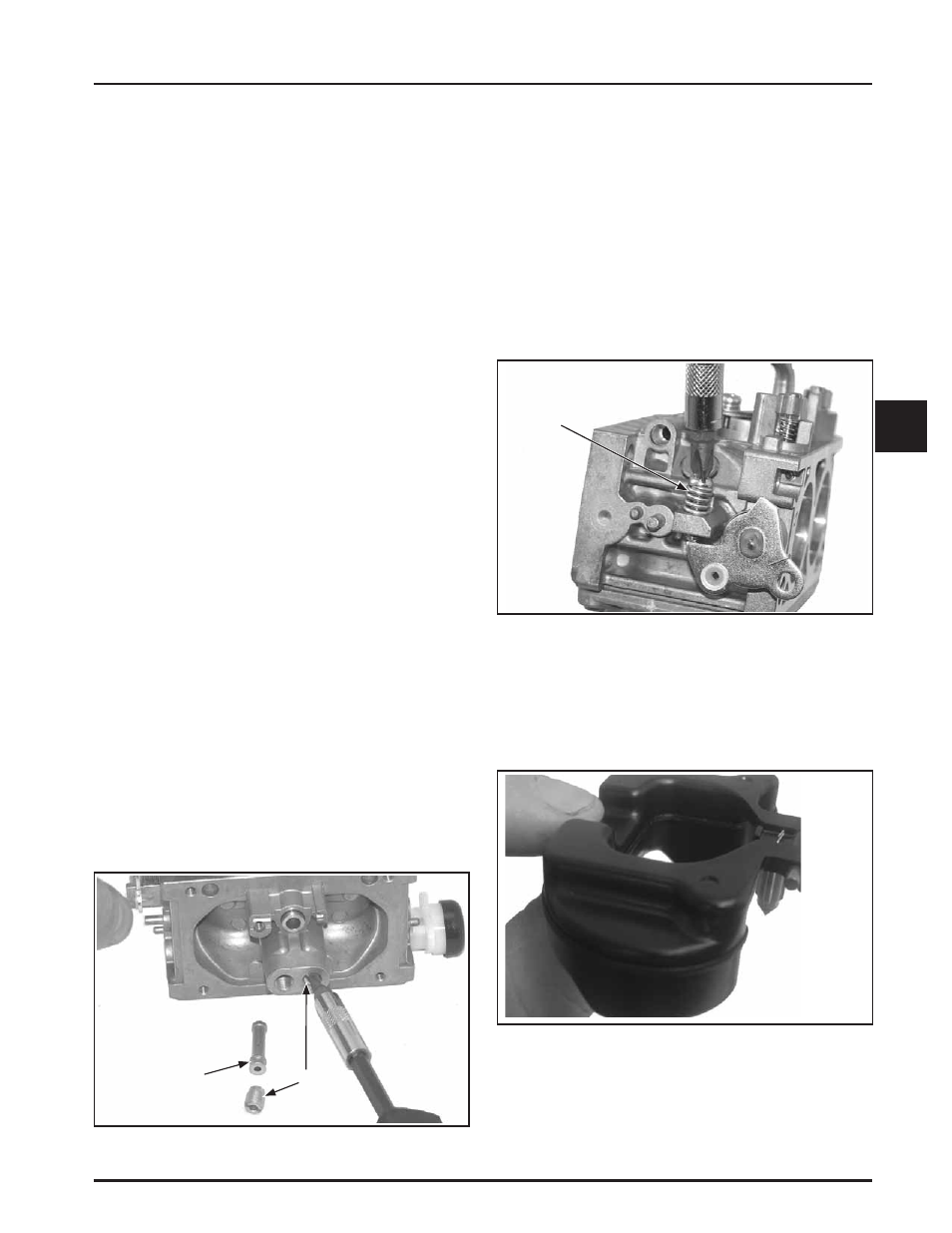
11. Install the new idle speed (RPM) adjustment
screw and spring onto the carburetor. Thread
in until 3 or 4 threads are exposed, as an initial
ǯȱȱȱśȬŘŚǯ
Figure 5-24. Installing Idle Speed Adjusting Screw
and Spring.
ŗŘǯȱ Ĵȱȱȱȱȱȱȱȱȱ
ȱĚȱ ȱȱ ȱǯȱȱȱşŖǚȱȱ
should point up, with the needle valve hanging
ǯȱȱȱśȬŘśǯ
Figure 5-25. Float and Inlet Needle Details.
ȱŗřǯȱ ȱȱĚȱȱȱȱ ȱȱȱ
seat and carburetor body. Install the new pivot
ȱȱȱĚȱȱȱȱ ȱȱ
ȱȱ ǯȱȱȱśȬŘŜǯ
Idle Speed
Screw and
Spring
Nozzle End with
Two Shoulders
(Out/Down)
Main
Jets