Part names and functions (vr-n900u) (continued) – JVC VR-N1600E User Manual
Page 22
14
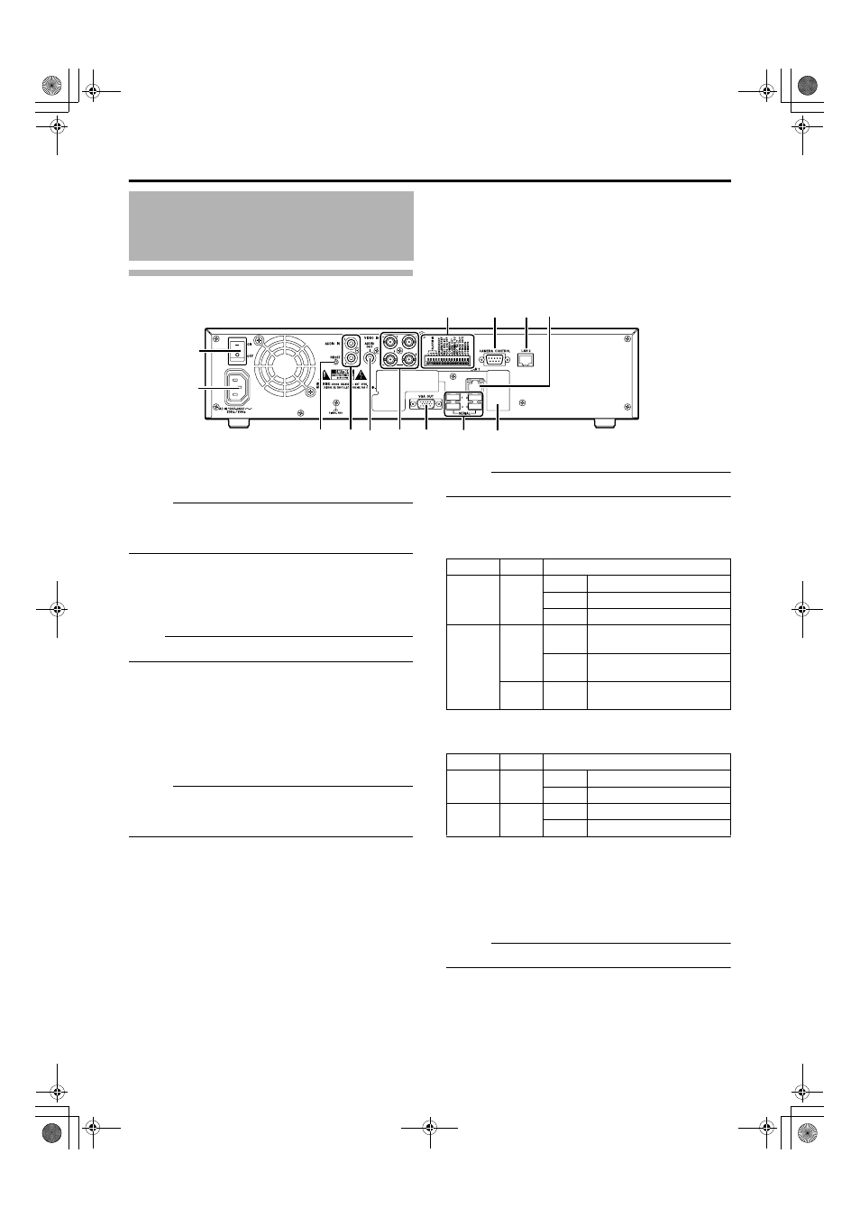
Rear Panel
W
[POWER] switch
Switches the power on or off.
Memo :
● Be sure to press and hold down the [OPERATE] button on the
front panel to shut down the system before switching off the
power supply.
X
[AC IN 120V-240VH 50Hz/60Hz] power input terminal
Connect to an AC outlet using the power cable supplied.
Y
[RESET]
Resets the system. Press this button when a malfunction occurs.
Note :
● Do not press this button in normal circumstances.
Z
[AUDIO IN 1/AUDIO IN 2] audio input terminals 1/2
(RCA)
Connect to the audio output terminal of the device from which audio
signals are to be recorded.
a
[AUDIO OUT] audio output terminal (RCA)
Outputs live sound in the live viewing mode.
Outputs recorded sound in the playback mode.
Memo :
● There is no audio output when playing back still images, when
running searches other than x1, or when playing back frame-by-
frame.
b
[VIDEO IN1 to 4] camera video signal input terminals
1 to 4
Connect to the video output terminal of the analog camera (sold
separately).
c
[VGA OUT] VGA output terminal
Outputs live images, recorded images and the menu screens.
d
[SERIAL1 to 4] serial terminals 1 to 4
For connecting the communication control terminals on a mouse
(sold separately), flash memory (sold separately), UPS (sold
separately) or additional disk drive (sold separately).
e
Connector cover
Memo :
● Do not remove the cover.
f
[LAN1] LAN1 connection terminal (camera network)
For connecting to the IP camera (sold separately) network using a
LAN cable.
g
[LAN2] LAN2 connection terminal (Intranet)
For connecting to the remote PC network using a LAN cable.
h
[CAMERA CONTROL] camera control terminal
Lets you control the analog cameras.
i
Signal input/output terminals
For operating VR-N1600 using external alarm signals or signals
received from external devices, or for operating external devices by
outputting signals.
Memo :
● Diameter of applicable cable: AWG22 to AWG28
Part Names and Functions
(VR-N900U) (continued)
W
X
c
Y
d
Z
a
b
h
i
f
g
e
Color
Status
Left
Indicator
Orange
Off
Not connected to the network.
On
Connected to the network.
Blinking
Communicating.
Right
Indicator
Green
Off
Communicating at 10 Mbit/
second.
On
Communicating at 100 Mbit/
second.
Orange
On
Communicating at 1 Gbit/
second.
Color
Status
Left
Indicator
Green
Off
Not connected to the network.
Blinking
Connected to the network.
Right
Indicator
Green
Off
Not communicating.
Blinking
Communicating.
VR-N1600_J.book Page 14 Tuesday, June 3, 2008 2:26 PM