Db25bo screw terminal breakout board, Ss-io/ss-io-6 cables, Pin connector db25bo on impulse drive – Impulse PCW-5181 User Manual
Page 84: Chapter 6 - hardware reference 6-8
Chapter 6 - Hardware Reference
6-8
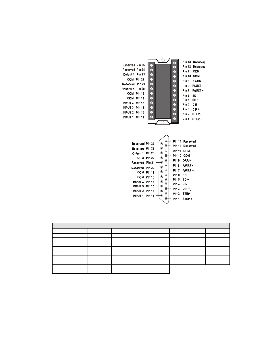
DB25BO Screw Terminal Breakout Board
When connected to the Impulse, the DB25BO terminals will match the pinouts of the 25-pin
connector as shown below.
SS-IO/SS-IO-6 Cables
25-pin Connector
DB25BO
on Impulse Drive
DB25BO
Screw
Terminal
Breakout
Board
IDC Cable P/N: SS-IO/SS-IO-6
Pin
Impulse Signal
Wire Color
Pin
Impulse Signal
Wire Color
Pin
Impulse Signal
Wire Color
1
STEP +
Brown
10
COM
Gray
19
COM
Black/White
2
STEP -
Red
11
COM
White
20
Reserved
Red/Black
3
DIR +
Orange
12
Reserved
Black
21
Reserved
Orange/Black
4
DIR -
Pink
13
Reserved
Brown/White
22
COM
Yellow/Black
5
SD +
Yellow
14
INPUT 1
Red/White
23
Output 1
Green/Black
6
SD -
Green
15
INPUT 2
Orange/White
24
Reserved
Gray/Black
7
FAULT +
Light Green
16
INPUT 3
Green/White
25
Reserved
Pink/Black
8
FAULT -
Blue
17
INPUT 4
Blue/White
Note: Cable SHIELD is internally connected to
the DB25 metal housing.
9
Drain
Violet
18
COM
Violet/White