Step, direction, and shutdown inputs fault output – Impulse PCW-5181 User Manual
Page 81
Chapter 6 - Hardware Reference
6-5
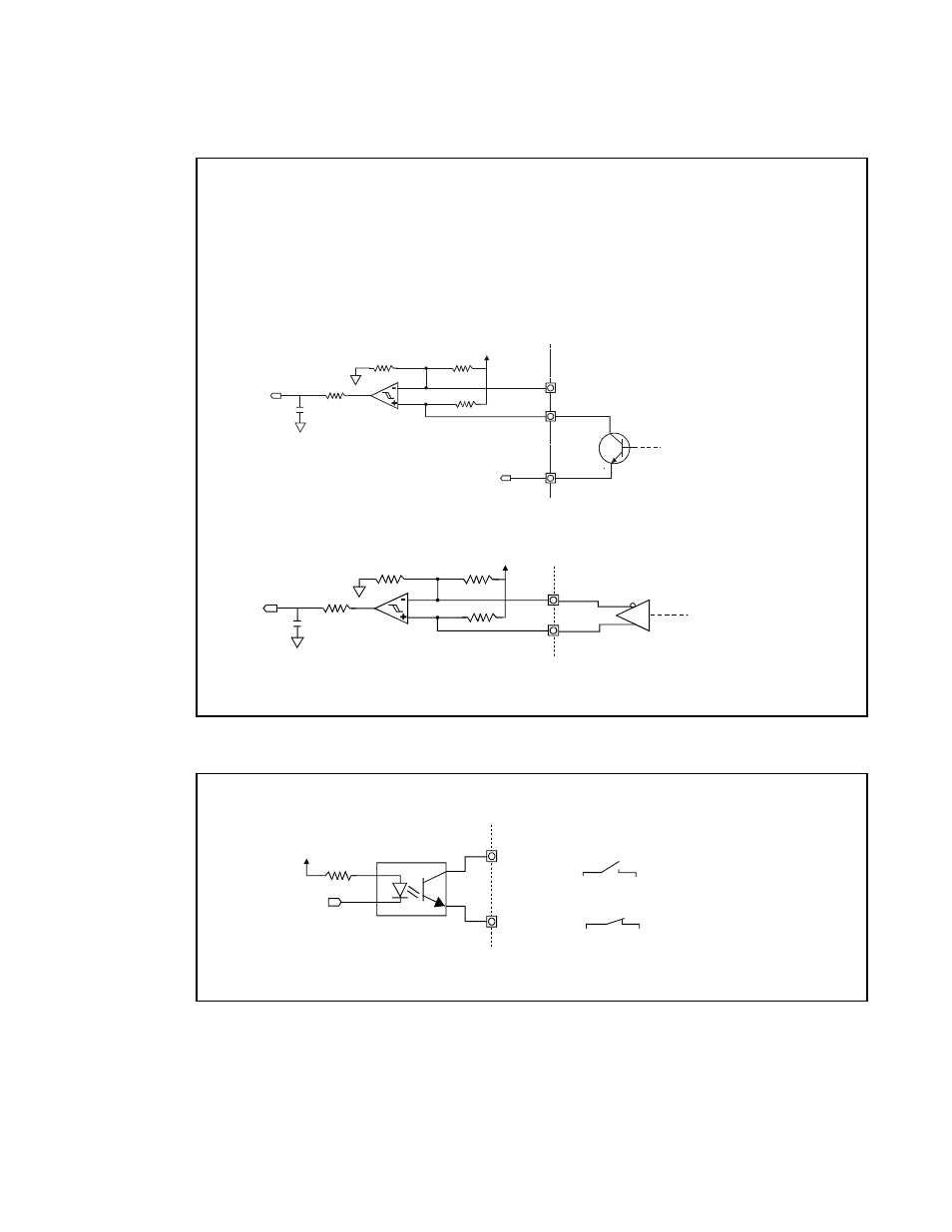
Step, Direction, and Shutdown Inputs
Fault Output
2.2n 50V
COM
COM
237
4.99K
4.99K
+5V
4.99K
AM26LS32
DIFFERENTIAL
DRIVER
STEP-
DIR-
SD-
STEP+
DIR+
SD+
Single-Ended
Installation
Application Notes:
1.When wiring TTL signals to other manufacturer’s indexers, the Step TTL command signals from
the controller should be wired to Step +, the Direction signal to Dir +, and the Shutdown signal
to SD + (Step -, Dir -, and SD - should not be connected). Remember to connect commons.
2.Activating the Shutdown input (logic low) disables the drive amplifier and de-energizes the motor.
When this input is off (logic high) the drive is enabled and the motor is energized.
external
Impulse internal
Impulse internal
external
Differential
Installation
2.2n 50V
237
4.99K
4.99K
4.99K
COM
COM
COM
+5V
STEP-
DIR-
SD-
STEP+, DIR+, SD+
SINKING
OUTPUT
COM
237
+5V
FAULT
FAULT+
FAULT-
4N35
NC
FAULT+
FAULT-
FAULT+
FAULT-
EQUIVALENT
CIRCUITS
external
Impulse internal
Drive Faulted
No Fault Present