FUJITSU T5440 User Manual
Page 163
Servicing Field-Replaceable Units
141
2. Remove the flex cable retainer.
Loosen the captive No.2 Phillips screw and lift the retainer up and out of the
chassis.
3. Unplug the flex cable from J9801 on the motherboard.
4. Unplug the auxiliary power cable from J9803 on the motherboard.
5. Unplug the front I/O connector from J9901 on the motherboard.
6. Remove the six No. 2 Phillips screws that secure the bus bar assembly to the
motherboard.
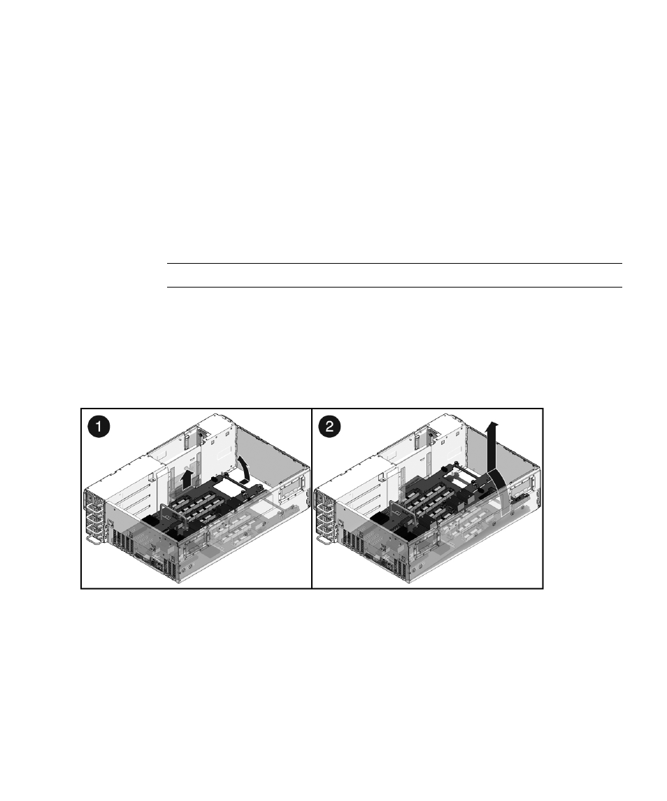
7. Slide the chassis midwall panel up.
Note –
Use the clips to secure the midwall panel in the open position.
8. Loosen the No. 2 Phillips screws that secure the motherboard to the chassis
floor.
See
“Motherboard Fastener Locations” on page 143
for the fastener locations.
9. Lift the motherboard up and out of the chassis.
Guide the flex cable connector out from under the midwall partition.
10. Place the motherboard on an antistatic mat.
Next Steps
If you are replacing a faulty motherboard, you must program the chassis serial
number and product part number into the new motherboard. See your service
representative.