3 connecting idec smartrelay inputs, Connecting idec smartrelay inputs, Idec smartrelay installation and wiring – IDEC FL1E SmartRelay User Manual
Page 49
IDEC SmartRelay installation and wiring
IDEC SmartRelay Manual
35
2.3.3
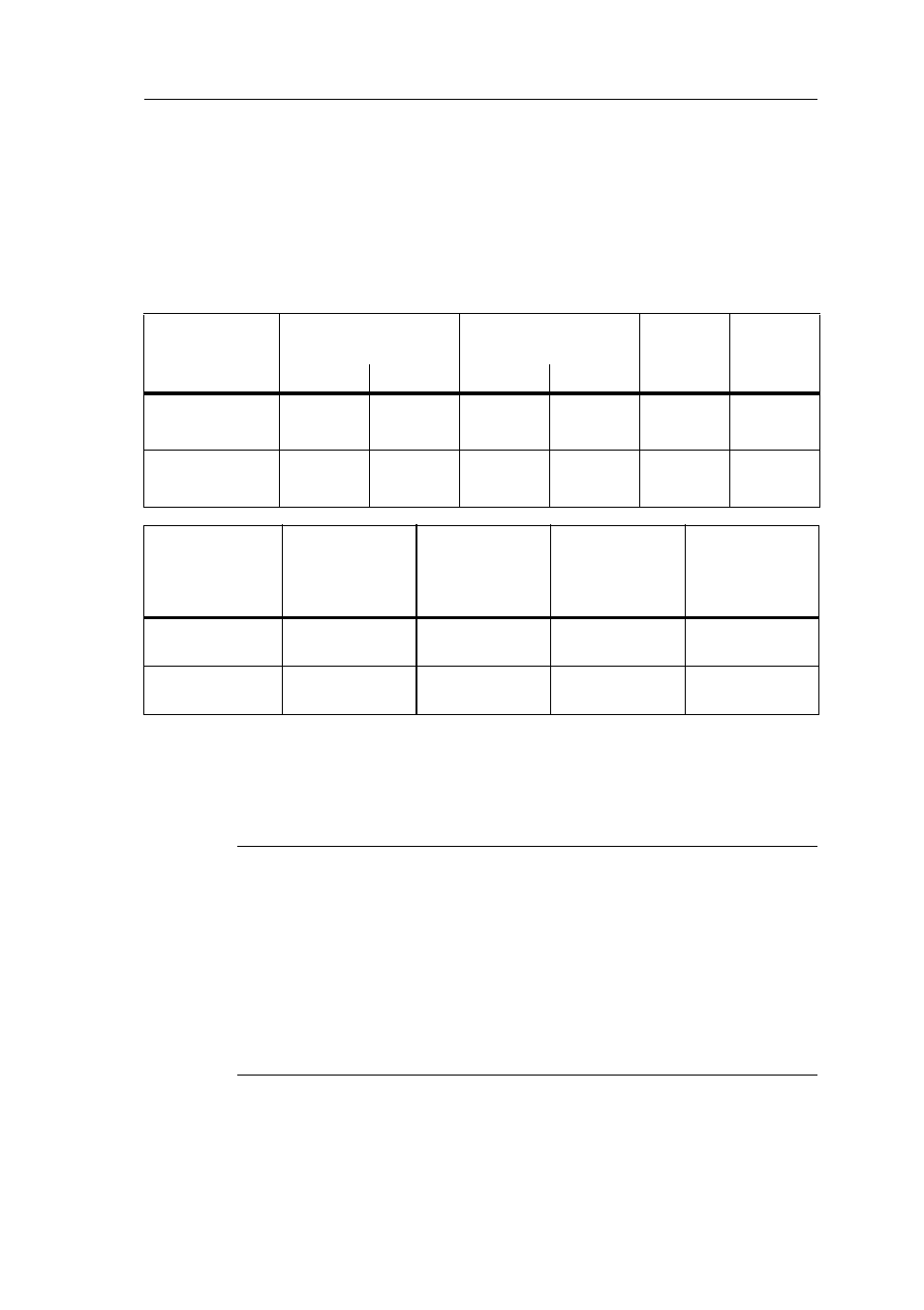
Connecting IDEC SmartRelay inputs
Requirements
At the inputs you connect sensor elements such as:
momentary pushbuttons, switches, light barriers, daylight
control switches etc.
Sensor characteristics for IDEC SmartRelay
(1): 1.0 mA (Version 1 to 5 specifications)
(2): 8 V DC (Version 1 to 5 specifications)
(3): 1.0 mA (Version 1 to 4 specifications)
(4): 8 V DC (Version 1 to 4 specifications)
(5): 1.5 mA (Version 1 to 4 specifications)
Note
The digital inputs of FL1E-H12RCC/FL1E-B12RCC are divided into
two groups, each consisting of four inputs. Within the same group,
all inputs must be operated on the same phase. Different phases
are only possible between the groups.
Example: I1 to I4 on phase L1, I5 to I8 on phase L2.
Inputs within the FL1B-M08C2R2 may not be connected to
different phases.
FL1E-H12RCE/
FL1E-B12RCE
FL1E-H12SND
FL1B-
M08B2R2
FL1B-
M08B1S2
I3 ... I6
I1,I2,I7,I8
I3 ... I6
I1,I2,I7,I8
I1 ... I8
I1 ... I8
Signal status 0 < 5 V DC < 5 V DC < 5 V DC < 5 V DC < 5 V DC < 5 V DC
Input current
< 0.85 mA < 0.05 mA < 0.85 mA < 0.05 mA < 0.85 mA
(1)
< 0.85 mA
(3)
Signal status 1 > 8.5 V DC > 8.5 V DC > 12 V DC > 12 V DC > 8.5 V DC
(2)
> 12 V DC
(4)
Input current
> 1.5 mA
> 0.1 mA
> 2 mA
> 0.15 mA
> 1.5 mA
> 2 mA
(5)
FL1E-H12RCA/
FL1E-B12RCA
FL1B-
M08D2R2 (AC)
FL1E-H12RCA/
FL1E-B12RCA
FL1B-
M08D2R2 (DC)
FL1E-H12RCC/
FL1E-B12RCC
FL1B-
M08C2R2 (AC)
FL1E-H12RCC/
FL1E-B12RCC
FL1B-
M08C2R2 (AC)
Signal status 0
Input current
< 5 V AC
< 1.0 mA
< 5 V DC
< 1.0 mA
< 40 V AC
< 0.03 mA
< 30 V DC
< 0.03 mA
Signal status 1
Input current
> 12 V AC
> 2.5 mA
> 12 V DC
> 2.5 mA
> 79 V AC
> 0.08 mA
> 79 V DC
> 0.08 mA