Idec smartrelay functions, Idec smartrelay manual 111, Inputs outputs analog inputs analog outputs – IDEC FL1E SmartRelay User Manual
Page 125
IDEC SmartRelay functions
IDEC SmartRelay Manual
111
There are also 16 blank outputs available. These are
identified with an x and cannot be reused in a circuit program
(in contrast to memory markers, for example). The list shows
all programmed blank outputs, and one blank output which
is not yet configured. A blank output, for example, is useful
for the special function ”Message texts” (see Chapter
4.4.23), if only the message text is of significance to a circuit
program.
2) Analog outputs
Analog outputs are identified by the letters AQ. Two analog
outputs are available, namely AQ1 and AQ2. An analog
output can only be connected with the analog input of a
function, an analog memory marker AM or an analog output
connector.
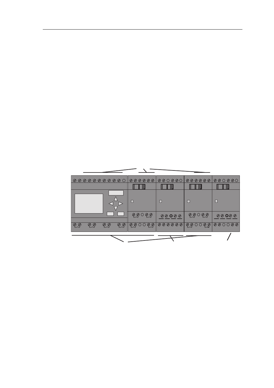
The following figure shows an example IDEC SmartRelay
configuration and the numbering of the inputs and outputs
for the circuit program.
L+ M I13I14 I15 I16
Q11
Q9
Q12
Q10
RUN/STOP
L+ M
AI5
RUN/STOP
L+ M AI3 AI4 I3 I4 I5 I6
Q1
Q2
Q3
Q4
AI1 AI2
L+ M I9 I10 I11I12
Q7
Q5
Q8
Q6
RUN/STOP
M3U3AI6M4 U4
1 2 1 2
1 2 1 2
1 2 1 2 1 2 1 2
1 2 1 2
1 2 1 2
PE
INPUT 2x (..10V/..20mA)
L+ M
L+ M
RUN/STOP
M1
V1+
L+ M
PE
OUTPUT 2x (0 ..10V)
M2
V2+
Inputs
Outputs
Analog inputs
Analog outputs
Memory Markers
Memory Markers are identified by the letters M or AM . These are
virtual outputs, which output the value of their inputs. IDEC Smart-
Relay provides 27 digital memory markers M1 ... M27 and 6 analog
memory markers AM1 ... AM6.
Startup Marker
Marker M8 is set in the first cycle of the user program and
can thus be used in your circuit program as a startup marker.
This signal is automatically reset after the circuit program
has completed its first cycle.
The M8 marker can be used in all further cycles for setting,
deletion and evaluation procedures in the same way as other
markers.