15 frequency trigger, Frequency trigger – IDEC FL1E SmartRelay User Manual
Page 182
IDEC SmartRelay functions
168
IDEC SmartRelay Manual
4.4.15 Frequency trigger
Short description
The output is set and reset with two configurable frequency
triggers.
Parameter G_T
The gate time G_T can be provided by the actual value of
another already-programmed function. You can use the
actual values of the following functions:
• Analog comparator (actual value Ax - Ay, see Chapter
• Analog trigger (actual value Ax, see Chapter 4.4.16)
• Analog amplifier (actual value Ax, see Chapter 4.4.20)
• Analog multiplexer (actual value AQ, see Chapter 4.4.26)
• Analog ramp control (actual value AQ, see Chapter
• Analog math (actual value AQ, see Chapter 4.4.30)
• PI controller (actual value AQ, see Chapter 4.4.28)
• Up/down counter (actual value Cnt, see Chapter 4.4.13)
Select the required function by the block number.
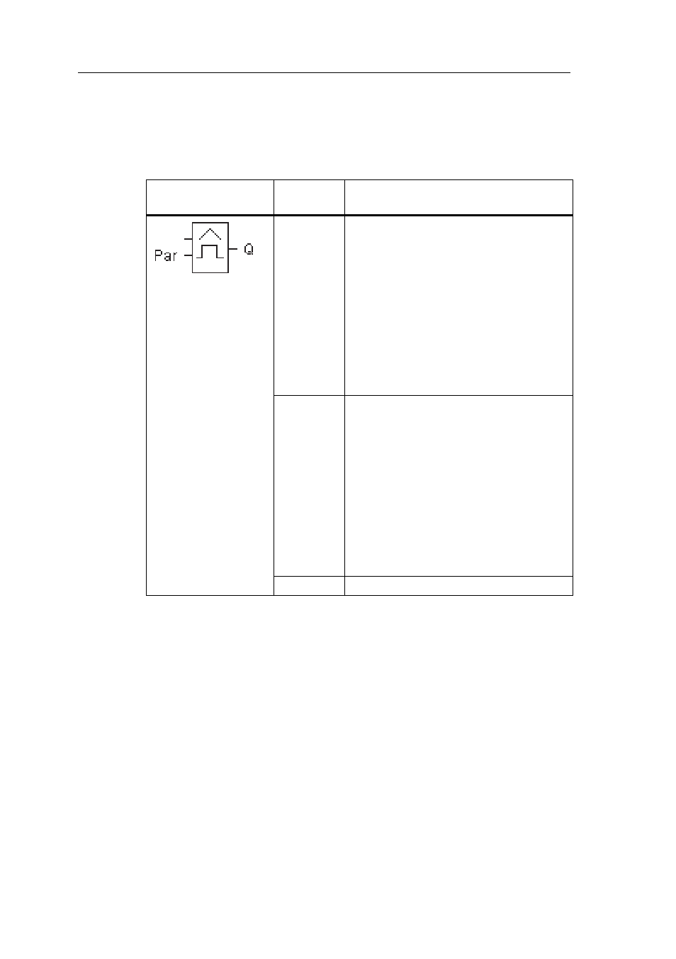
Symbol in IDEC
SmartRelay
Wiring
Description
Input Fre
The function counts the 0 to 1
transitions at input Fre. 1 to 0
transitions are not counted.
Use
• inputs I3, I4, I5, I6 for fast counting
(only FL1E-H12RCE/FL1E-
B12RCE and FL1E-H12SND): max.
5 kHz.
• any other input or circuit component
for counting low frequency signals
(typ. 4 Hz).
Parameter On : On threshold
Range of values:
0000...9999
Off : Off threshold
Range of values:
0000...9999
G_T : Time interval or gate time during
which the input pulses are
measured.
Range of values:
00:05 s...99:99 s
Output Q
Q is set and reset at the thresholds.
Fre