IDEC FL1E SmartRelay User Manual
Page 37
IDEC SmartRelay installation and wiring
IDEC SmartRelay Manual
23
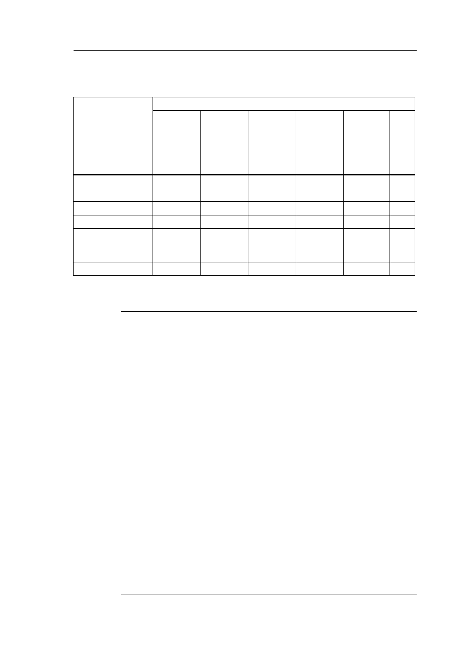
Overview: Connecting an additional expansion module to an
expansion module
When setting up expansion modules of different power volt-
ages, take the following restrictions into consideration.
Note
When you use a 24V DC power supply to supply power to 12/24V
DC power type base module and 24V DC power type expansion
I/O modules, use a 24V DC power supply which starts up within 10
seconds, otherwise the base module does not recognize the
expansion I/O modules. When the power supply voltage varies
while the base module and the expansion I/O modules are
operating, they normally operate within the permissible operating
voltage range.
When using different power supplies, supply power to the base
module and expansion modules at the same time, or supply power
to expansion modules before the base module.When supplying
power to expansion modules after the base module, expansion
modules may not be recognized by the base module.
When using different power supplies, the fast transient/burst
immunity (IEC61000-4-4) will be 1 kV (power supply).
A 100 to 240V AC/DC module cannot be connected to the right side
of a 12/24V DC, 24V DC, or 24V AC/DC module.
For analog input module and AS-Interface communication module,
a module of any voltage can be connected to the left side. To the
right side, however, a 100 to 240V AC/DC module cannot be
connected.
Expansion
module
Additional expansion modules
FL1B-
M08B2R2
FL1B-
M08B1S2
FL1B-
M08D2R2
FL1B-
M08C2R2
FL1B-
J2B2,
FL1D-
K2B2,
FL1D-
K2BM2
CM
FL1B-M08B2R2
x
x
x
-
x
x
FL1B-M08B1S2
x
x
x
-
x
x
FL1B-M08D2R2
x
x
x
-
x
x
FL1B-M08C2R2
-
-
-
x
x
x
FL1B-J2B2,
FL1D-K2B2
FL1D-K2BM2
x
x
x
-
x
x
CM AS Interface
x
x
x
-
x
x