Connectors, Connectors -9 – Anritsu Series MS278XB User Manual
Page 61
Instrument Overview
Front Panel Overview
MS278XB OM
3-9
Connectors
The front panel connectors consist of the following:
• Probe Power Port: This port supplies power to your power probe. Table 3-2 shows the probe power port
pinout.
• Tracking Generator Output Port: Not used at this time.
• RF Input Port: Ruggedized N-style connector, +30 dBm @ 50
Ω, MAXIMUM ZERO (0) Volts DC from
100 Hz to 8 GHz input.
• Source Output Port: Not used at this time.
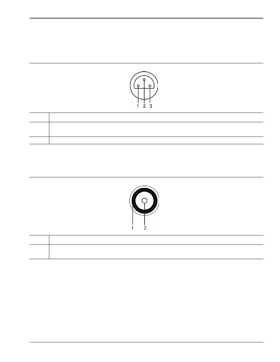
Table 3-2.
Probe Power Port Pinout
Pin
Description
1
+15 Vdc at 130 mA
2
Ground
3
-12.6 Vdc at 45 mA
Table 3-3.
RF Input Port
Pin
Description
1
Outer Shield and Screw Fastener
2
Center Pin