Checking the usb audio input/output levels, Assigning functions to foot switches or drum, Triggers – Roland TM-6 Pro Drum Trigger Module User Manual
Page 43: P. 43, O “assigning functions to foot, Switches or drum triggers” (p. 43), Iggers (p. 43), Assigning a function to a footswitch, Assigning a function to a drum trigger, Settings (menu)
43
Settings (MENU)
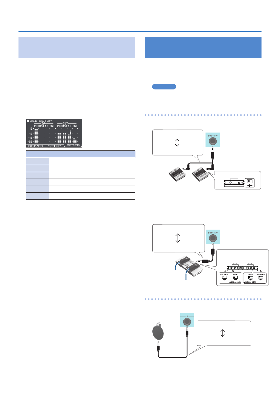
Checking the USB Audio Input/Output
Levels
Here’s how to check the input/output levels of the USB
audio.
1
In the SYSTEM screen (p. 38), select “USB
Setup” and press the [ENTER] button.
The USB SETUP screen appears.
2
Press the [F2] (METER) button.
The USB audio input/output levels are shown by the
meter.
Display
USB channel
Jack
PHO
Ch1, 2
PHONES OUT (L/R)
MST
Ch3, 4
MASTER OUT L, R
1
Ch5
DIRECT OUT 1
2
Ch6
DIRECT OUT 2
3
Ch7
DIRECT OUT 3
4
Ch8
DIRECT OUT 4
3
Press the [EXIT] button several times to
return to the KIT screen.
Assigning Functions to Foot Switches or
Drum Triggers
Foot switches (BOSS FS-5U, FS-6; sold separately) or
drum triggers that are connected to the TM-6 PRO can
be assigned to control functions such as switching kits or
switching set lists.
Reference
For details on the parameters that can be edited, refer to
“Data List” (PDF).
Assigning a function to a footswitch
Connecting an FS-5U
SW2
SW1
TIP
Stereo 1/4” phone type
1/4” phone type x 2
RING
POLARITY switch
* If you use a mono cable to connect a single FS-5U, it will
operate as SW 2.
* The FS-5L cannot be used.
Connecting an FS-6
Stereo 1/4” phone type
Stereo 1/4” phone type
SW2
SW1
MODE/POLARITY switch
Assigning a function to a drum trigger
You can assign a function to the drum trigger that is
connected to the TRIGGER IN 5 jack.
Stereo 1/4” phone type
Stereo 1/4” phone type