2 s0 input – KACO Powador XP500-XP550-HV TL outdoor User Manual
Page 91

Page 92
Operating Instructions Powador XP500/550-OD-TL
U s e r i n t e r f a c e
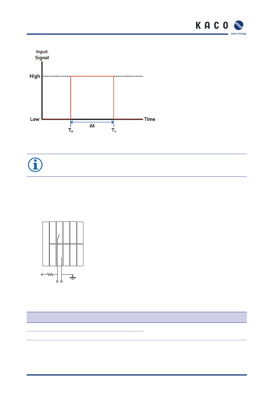
Figure 67: DI1 input signal
NOTE
The {DI1 Check Period} is parameter in ‘8.5 Digital Parameters’ that mean recognition
pattern period for inverter stop operation when selecting ‘DI1 Select’ to ‘5’.
9.1.2 S0
input
24Vdc
1c
1c
1d
1d
2c
2c
2d
2d
UDIO
0Vdc
4.7 kΩ
Input signal
3c
3c
3d
3d
4c
4c
4d
4d
5c
5c
5d
5d
Figure 68: Connection for S0 input
Terminal number
Terminal designation
Specifi cation
Wire cross- section
2c
S0
in
P
Max 27Vdc, 27mA
AWG 20
(0.518mm
2
)
2d
S0
in
N
Table 22: Connections for S0 input
