Yaskawa JAPMC-MC2303-E User Manual
Page 77
5.3 FL-net Data Communication
5.3.1 Cyclic Transmission
5-10
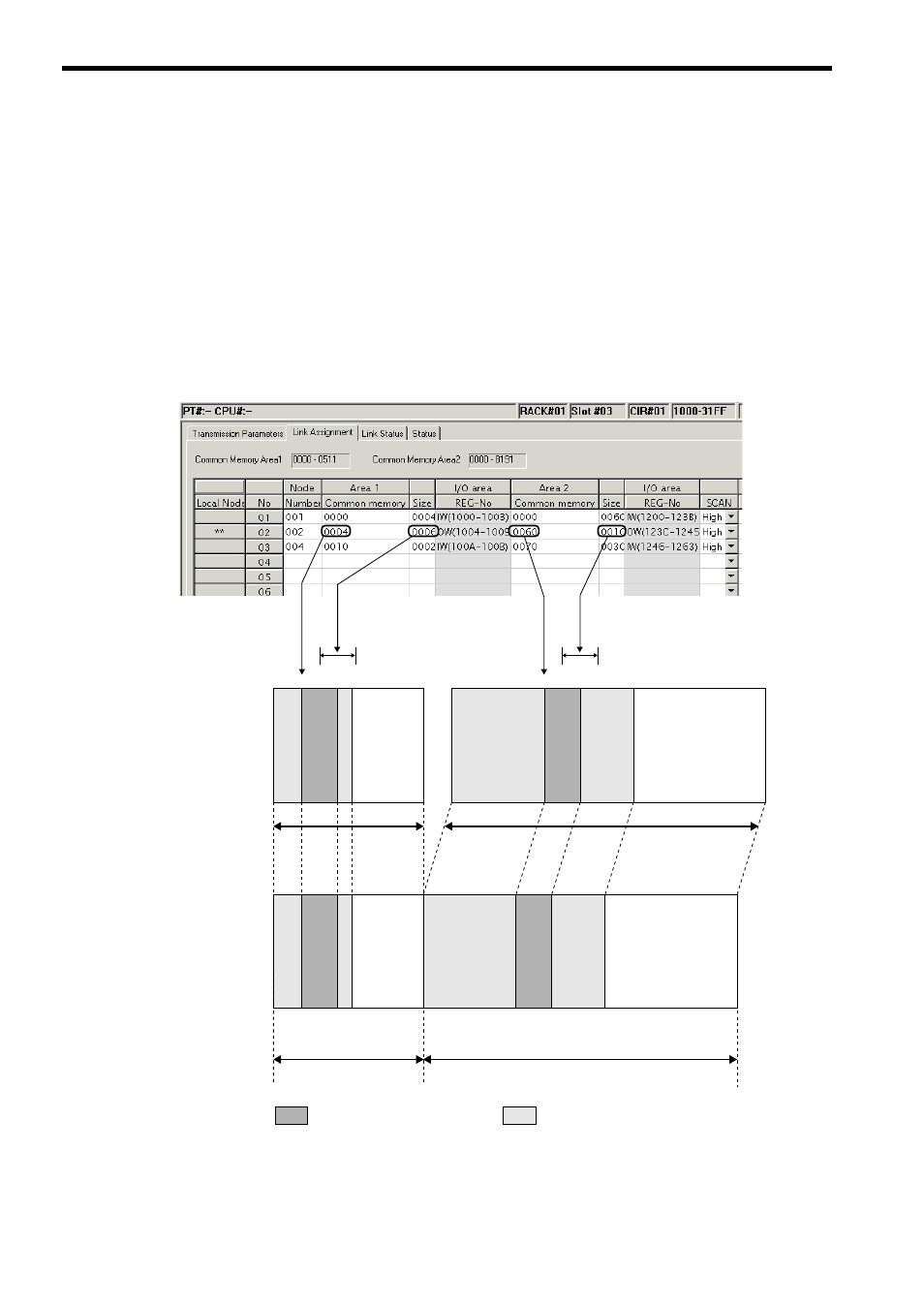
( 5 ) Assignment of I/O Register and Common Memory
The FL-net common memory function reads data from or writes it in each node area assigned for the CPU module I/O
registers (IW register, OW register). The 262IF-01 Module uses the engineering tool MPE720 for I/O register assign-
ment and defines the following four items.
• Node number
• Leading address and size of I/O registers
• Address and size of FL-net common memory area 1
• Address and size of FL-net common memory area 2
The following figure shows an assignment example of the FL-net common memory and I/O registers.
The local node areas 1 and 2 serve as the output register (OW) dedicated to sending, and other node areas 1 and 2 as the
input register (IW) dedicated to receiving.
The I/O registers (IW register, OW register) are defined as a continuous area consisting of areas 1 and 2, and are filled
starting with area 1. In link assignment definition, it is allowed to define only area 1 or area 2.
Set by Transmission Parameters
Tab Page
0000
0004
00100012
051
1
IW1000OW1004 IW100A
IW100C
IW1200
OW123C
IW1246
IW1264
IW31FF
6 words
0000
0060
0100
0070
8191
Area 1
Area 2
10 words
㧦Local node (OW register)
㧦Other node (IW register)
FL-net common memory
(Set by Link Assignment
Tab Page)
Node number 1 (input)
Node number 1 (input)
Node number 2 (output)
Node number 2 (output)
Node number 4 (input)
Node number 1 (input)
Node number 2 (output)
Node number 4 (input)
Node number 1 (input)
Node number 2 (output)
Node number 4 (input)
Node number 4 (input)
Common memory area 1 size
(variable in a range from
0 to 200H)
Common memory area 2 size (variable in a range from 0 to 2200H)
(I/O ending register number
− common memory area 1 size)
CPU Module I/O register