Yaskawa JAPMC-MC2303-E User Manual
Page 105
6.2 Message Receive Function
6.2.3 Inputs and Outputs for the Message Receive Function
6-20
[ f ] Ch-No (Channel Number)
The Ch-No input specifies the channel number of the transmission buffer.
Any channel number can be specified as long as it is within the valid range. If more than one function is being exe-
cuted at the same time, do not specify the same channel number more than once for the same modem number. (The
same channel number can be used as long as the functions are not executed at the same time.)
The valid channel number range of FL-net is 1 to 10.
In FL-net (262IF-01), there are 10 channels of transmission buffers from 1 to 10 for sending and receiving combined,
so up to 10 messages can be sent and received at the same time.
One MSG-RCV (or MSG-SND) function must be programmed for each circuit being used at the same time.
Refer to Conceptual Diagram of Transmission Buffer Channels on page 6-6 for information on transmission buffer
channels.
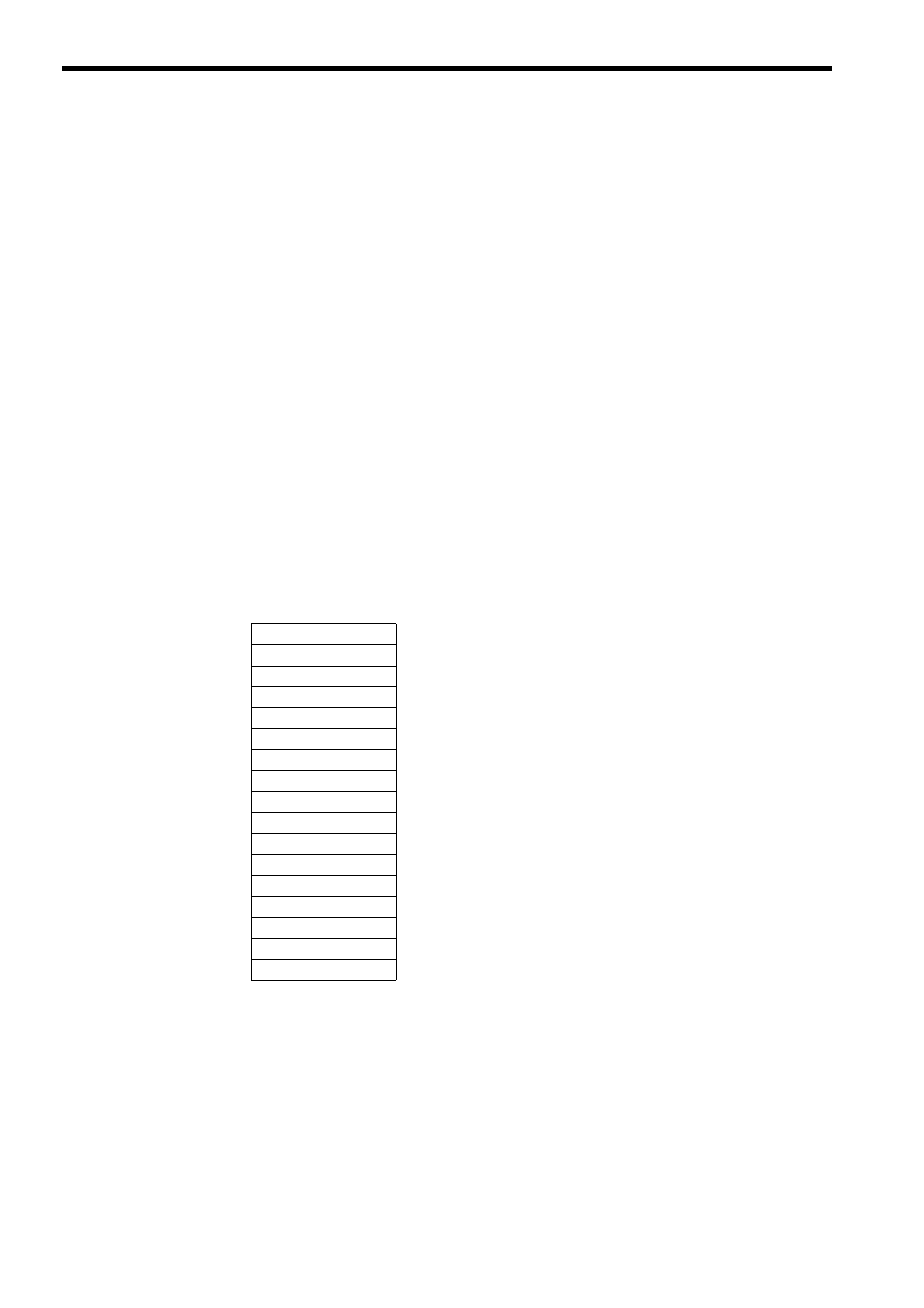
[ g ] Param (Parameter List Leading Address)
The PARAM input specifies the leading address of the parameter list. A parameter list will be automatically created
from the 17 words starting with the specified address. Use the parameter list to input the holding register offset value
and write range LO/HI. The processing results and connection number are also output to the parameter list.
Refer to 6.2.4 Parameter List for MSG-RCV Function on page 6-23 for information on the parameter list.
Example: The following parameter list will be created when the Parameter List Leading Address is set to
DA000000.
Register
Parameter
F
· · · · · · ·
0
DW000000
PARAM00
DW000001
PARAM01
DW000002
PARAM02
DW000003
PARAM03
DW000004
PARAM04
DW000005
PARAM05
DW000006
PARAM06
DW000007
PARAM07
DW000008
PARAM08
DW000009
PARAM09
DW000010
PARAM10
DW000011
PARAM11
DW000012
PARAM12
DW000013
PARAM13
DW000014
PARAM14
DW000015
PARAM15
DW000016
PARAM16